EN


Machine Vision Light Buying Guide for B2B Engineers
A machine vision light is not a finishing accessory for an inspection station. It establishes the image conditions that the camera, lens, and algorithm must work with. When a line has false rejects, washed-out codes, unstable edge detection, or inconsistent color classification, the root cause is often illumination geometry or stability, not the inspection software.
For B2B engineers, the right purchase decision starts with the part and the defect, then moves through optics, control, mechanical constraints, and supplier validation. This guide gives you a procurement-ready way to specify a machine vision light without treating a catalog photo or a peak-brightness value as proof of fit.
Start With the Inspection Question, Not the Light Type
Before comparing a ring light, bar light, dome light, coaxial light, or backlight, write down what the system must reveal. Is the task to find a shallow scratch, verify a silhouette, read a printed code, detect a missing component, or inspect a reflective surface? The same part can need different lighting when the target defect changes.
Document the surface finish, color range, shape, field of view, working distance, line speed, camera shutter mode, ambient-light exposure, and allowable fixture space. This turns a vague request for a bright machine vision light into a testable specification. It also prevents a common failure mode: selecting the light first and attempting to tune the vision algorithm around poor contrast later.
Match Illumination Geometry to the Image You Need
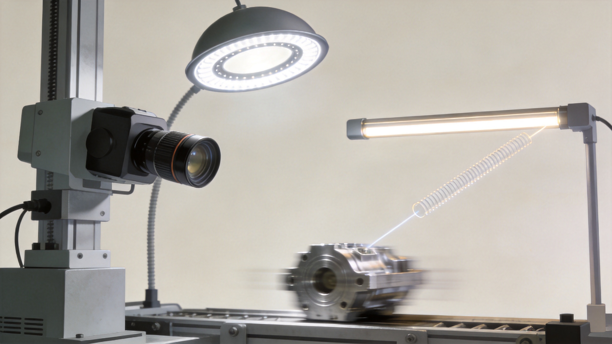
| Light geometry | Usually useful for | Selection caution |
|---|---|---|
| Ring light | General front illumination, flat targets, compact camera-centered setups | Highly reflective or cylindrical parts can show a specular ring that hides defects. |
| Bar light | Low-angle surface texture, scratch contrast, large fields of view, line-scan arrangements | Angle and mounting symmetry matter; a poor angle can create shadows instead of useful contrast. |
| Dome light | Curved, glossy, or irregular surfaces where diffuse light reduces harsh reflections | Very diffuse light can reduce the directional shadow contrast needed for shallow-scratch detection. |
| Coaxial light | Flat reflective surfaces, printed marks, PCB features, and some code-reading tasks | Confirm that the optical path and working distance fit the lens and mechanical envelope. |
| Backlight | Silhouette, edge, gap, presence/absence, and dimensional-outline inspection | Validate field uniformity across the full part travel range, not only at the image center. |
Ring lights are often treated as the default. They are convenient, but convenience is not the same as optical fit. On polished metal or glossy cylindrical parts, the reflected ring pattern may make edge or scratch detection harder. A low-angle bar arrangement, a diffuse dome, or a different machine vision light geometry may be the better starting point.
Evaluate Wavelength, Uniformity, and Intensity Together
Do not default to white light solely because it is familiar. Materials absorb and reflect wavelengths differently, so wavelength selection is a contrast decision. Red, blue, IR, UV, and narrow-band visible options should be evaluated against representative parts and the camera sensor response. A wavelength that improves separation between a target and its background can reduce downstream processing difficulty; it is not simply a color preference.
Brightness also needs context. The important question is whether the machine vision light delivers stable, usable illumination over the full inspection area at the required exposure time. The spec that teams often underweight is uniformity. A setup can look acceptable at the center of the field while producing lower contrast near the edges, where part position naturally varies on a production line.
Ask suppliers how they measure output and uniformity: working distance, drive current, diffuser configuration, ambient condition, and warm-up state all affect comparability. More light does not automatically improve the image. Sensor saturation can remove the gradients that make fine defects visible, while excess drive current can increase thermal load and reduce long-term stability. For this reason, compare each candidate machine vision light at the actual working distance instead of comparing a headline brightness number alone.
Specify the Controller and Trigger Interface Early
For high-speed inspection, the machine vision light and controller are a single purchasing decision. The camera exposure, trigger signal, strobe pulse width, peak current, duty cycle, and thermal limits must be compatible. Short-pulse overdrive can help freeze motion, but its usable limit depends on the controller, LED design, flash rate, and operating conditions. Do not assume that two products with a generic “strobe” label provide equivalent timing behavior.
Request interface details before purchase: trigger voltage and polarity, maximum switching rate, multi-channel control, analog or digital dimming, synchronization method, and any documented limits for continuous and pulsed operation. If a PLC or vision controller will manage illumination, include that integration path in the acceptance test.
Check Mechanical and Environmental Fit
A technically correct optical concept can still fail in the machine. Verify lens clearance, cable routing, bracket rigidity, heat dissipation, access for cleaning, and whether vibration can move the illumination footprint. Working distance links camera selection, lens choice, field of view, and light geometry; treat these as one system-level constraint.
For wash-down, dust, humidity, coolant mist, or outdoor exposure, define the actual environment before choosing an enclosure rating. Ask what the stated rating covers, including connector and cable-gland conditions. Higher ingress protection can be essential in harsh environments, but it is not a substitute for verifying thermal behavior, optical window cleanliness, and the installation details that affect real-life output.
Use a Controlled Sample Test Before Volume Approval
The most useful supplier conversation begins with representative parts, not a generic request for a quotation. Provide normal units, known-good units, and edge cases: finish changes, color variations, shallow defects, dimensional extremes, or samples from multiple production batches. Then evaluate each candidate machine vision light configuration at the production working distance and expected line speed.
Define acceptance criteria in image terms: contrast at the feature of interest, acceptable edge-to-center variation, exposure margin, repeatability after warm-up, trigger stability, and performance under realistic ambient-light conditions. If the final machine will run multiple part families, test them all. A light that works on matte black housings may behave very differently on metallic or glossy variants.
Qualify the Supplier as Carefully as the Light
A B2B purchase should assess continuity and support as well as optics. Ask for dimensional drawings, wiring documentation, controller manuals, test conditions behind published specifications, lead-time guidance, replacement policy, and available compliance documents for your market. IEC/EN 62471 is one relevant photobiological-safety evaluation framework for LED lighting; whether it applies to your project depends on the product, wavelength, intensity, and deployment conditions, so request documentation where it is relevant rather than assuming it is universal.
HIFLY supports a broader machine vision ecosystem that includes lights, cameras, lenses, and controllers. That can be useful when an engineering team needs to evaluate component compatibility together, rather than treating illumination as an isolated purchase. For a custom or high-risk application, give the supplier the part drawings, sample images, camera details, lens information, working distance, and required cycle time so the recommendation can be tested against your actual constraints.
A Practical Machine Vision Light Buying Checklist
- Define the inspection feature and the surface property that makes it difficult to see.
- Select candidate geometry based on directional, diffuse, coaxial, or backlit illumination needs.
- Test wavelength against the target material and camera sensor response.
- Verify uniformity across the complete field of view and expected part-position tolerance.
- Match controller timing, trigger interface, pulse capability, and thermal limits to the required exposure.
- Confirm working distance, mounting clearance, cabling, vibration resistance, and environmental protection.
- Run a controlled test with representative parts before approving volume procurement.
- Review documentation, replacement continuity, technical support, and relevant compliance evidence.
Make the Purchase Decision on Repeatability
The appropriate machine vision light creates repeatable contrast for the specific inspection task while fitting the camera, lens, controller, machine envelope, and maintenance plan. That process can take longer than selecting the brightest catalog option, but it reduces integration iterations and makes the system easier to validate, maintain, and scale across lines.
Use the checklist to narrow the optical concept, then validate it with real parts. That sequence gives procurement teams a clearer basis for comparison and gives engineering teams an illumination setup they can defend long after commissioning.