EN
EN


Machine Vision Light Controller Buying Guide for OEMs
For an OEM, a machine vision light controller is not simply a power supply placed between a light and a camera. It is the timing and current-management layer that helps make inspection images repeatable across production cycles, stations, and product variants. A light may look bright enough during a bench test yet still produce unstable images if the controller cannot deliver the intended current, synchronize reliably with the camera, or handle heat under the real duty cycle.
This guide gives engineering, sourcing, and program teams a practical way to specify a machine vision light controller. It focuses on the questions that prevent late integration changes: how the controller will run, what it must drive, how it will receive triggers, and how the team will validate the finished vision cell.
Start With the Inspection Task, Not the Controller Catalog
A sound controller choice begins with the defect or feature the camera must see. List the material, surface finish, object speed, field of view, camera exposure, lens aperture, and acceptable inspection variability. These facts determine whether continuous illumination is sufficient or whether a short synchronized pulse is more suitable.
A machine vision light controller commonly supports continuous operation, strobe operation, or both. Continuous mode supplies a stable output for applications with fixed exposure and moderate brightness needs. Strobe mode coordinates a light pulse with a camera or system trigger, which can help freeze motion or increase usable intensity during a short exposure. The right choice depends on the whole imaging budget; it should not be selected merely because a controller has a strobe label.
- Static or slow-moving parts: evaluate continuous operation first, then verify uniformity and thermal behavior.
- Fast conveyors or rotating components: define exposure, trigger latency, and pulse width together before choosing a strobe-capable controller.
- Mixed recipes: confirm that operating modes, saved settings, and remote control behavior can be changed safely between products.
Match Electrical Output to the Light You Actually Plan to Use
Every machine vision light controller must be checked against the intended illumination device, not just against a broad light category. Compare the controller’s output method, channel count, allowed current range, voltage range, connector arrangement, and operating mode with the light documentation. Verify whether the light expects constant-current drive, what current it permits in continuous service, and whether it allows pulsed operation.
Do not assume that a higher-rated controller improves an image. Excess electrical capacity can be useful for design margin, but it does not replace a compatible current range or a thermal plan. Conversely, a controller that appears adequate at nominal output may be unsuitable when several channels operate at the production duty cycle.
Questions for the electrical review
- How many independently controlled light channels are required now, and what expansion margin is needed?
- What current and voltage does each light require in continuous and pulsed use?
- Are the light, controller, cable, and connector compatible as a complete assembly?
- Does the design require current monitoring, fault indication, or a defined safe-state behavior?
- What happens if the system starts with an invalid recipe or loses a trigger signal?
Specify Timing as a System Interface
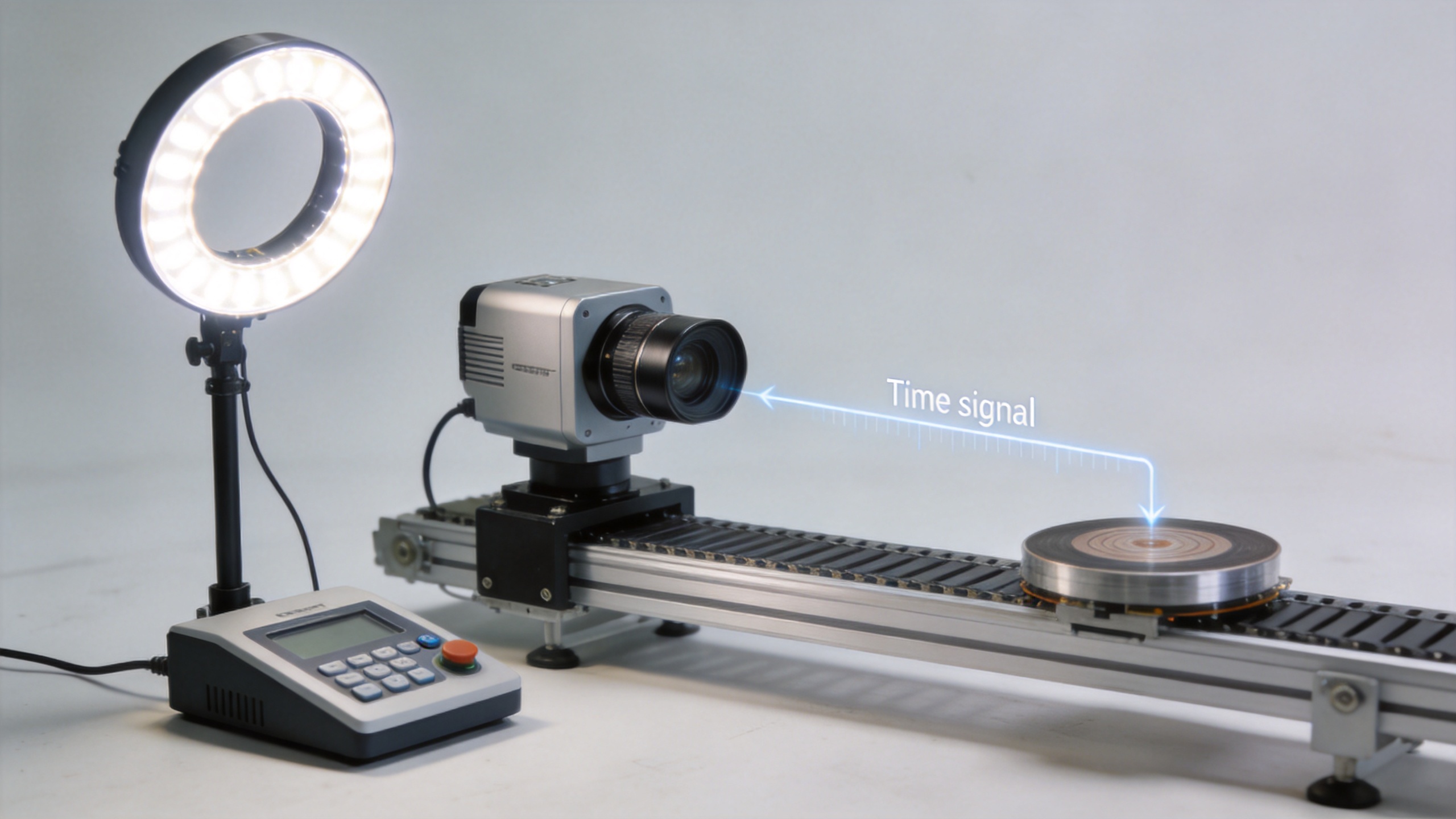
Timing is often the deciding factor in a machine vision light controller purchase. The controller must fit the camera trigger scheme, PLC or motion-control signals, and the light’s permitted pulse behavior. Document signal type, polarity, trigger source, isolation needs, expected latency, jitter tolerance, pulse width, and whether the controller must expose a ready or fault output.
For high-speed inspection, use a timing diagram during supplier review. Show the part position, sensor event, camera exposure, controller trigger, light pulse, and image acquisition window. This makes hidden assumptions visible before hardware reaches the line. A controller that can synchronize light pulses with camera and trigger signals may be appropriate, but the OEM still needs to prove the complete timing chain under production conditions.
Evaluate Thermal and Duty-Cycle Limits Early
Brightness, pulse width, repetition rate, ambient temperature, enclosure airflow, and the number of active channels all affect thermal performance. Ask suppliers for the operating conditions behind any output rating, then calculate the expected duty cycle for the actual station. Include warm-up, continuous operation, cleaning cycles, and the highest planned line rate.
During a pilot test, inspect image stability after the system has reached thermal equilibrium. A controller-light combination that performs well during a brief demonstration can behave differently after hours of repeated operation. Include temperature-related checks in your factory acceptance criteria rather than treating thermal behavior as a later maintenance issue.
Choose the Control and I/O Architecture for Your OEM Platform
OEM programs benefit when the machine vision light controller fits a repeatable controls architecture. Define the required local controls, digital I/O, analog control, serial or Ethernet communication, recipe management, and diagnostic access. The controller should be practical for commissioning engineers and maintainable for production teams.
| Integration topic | What to confirm | Why it matters |
|---|---|---|
| Trigger interface | Signal levels, polarity, isolation, timing behavior | Prevents intermittent image capture or missed pulses |
| Remote control | Protocol, command set, settings retention, error reporting | Supports recipe changes and traceable commissioning |
| Diagnostics | Overcurrent, overtemperature, open-load, and fault outputs | Helps reduce troubleshooting time on the production floor |
| Mechanical integration | Mounting, cable routing, enclosure conditions, service access | Reduces redesign work during machine build |
Build Supplier Evaluation Around Compatibility and Support
Component price is only one part of the OEM decision. A machine vision light controller should be evaluated with its lighting, camera, lens, and controls interfaces in mind. HIFLY’s established machine vision portfolio can be relevant when a project team needs coordinated discussions across lights, cameras, lenses, and controllers rather than isolated component selection. That does not eliminate validation; it makes it easier to review system interfaces with a single technical context.
For custom machines, ask how the supplier handles connector changes, housing constraints, special triggering needs, documentation revisions, and production continuity. Confirm lead-time communication, revision control, sample availability, and technical support escalation before releasing a design to volume manufacturing.
Run a Pilot Test Before Design Freeze
A short, disciplined pilot is more valuable than a feature checklist. Test the selected machine vision light controller with the final or representative light, camera, lens, cable length, and application software. Use real parts that include normal variation and known defects.
- Capture images at the target speed, exposure, and illumination setting.
- Repeat tests after thermal stabilization and after planned stop-start cycles.
- Verify trigger timing at the limits of expected line-speed variation.
- Record controller settings, image-quality criteria, alarms, and recovery behavior.
- Check that a replacement controller can be configured consistently through the documented process.
OEM Buying Checklist
Before issuing a purchase order, make sure your specification answers the following:
- What inspection feature, exposure condition, and throughput must the lighting system support?
- Is continuous, strobed, or mixed operation required?
- Are current, voltage, channels, connectors, and cables validated against the selected light?
- Is the trigger diagram approved by vision, controls, and mechanical teams?
- Are thermal limits and duty cycle verified in the actual enclosure conditions?
- Do I/O, communications, diagnostics, and recipe controls fit the machine platform?
- Have pilot tests established measurable image and fault-handling acceptance criteria?
- Can the supplier support revisions, documentation, and repeat production needs?
Conclusion
A well-chosen machine vision light controller protects image consistency and reduces integration uncertainty. Treat it as a system component with electrical, timing, thermal, and service requirements—not as an interchangeable accessory. When OEM teams define these interfaces early, validate the controller-light-camera combination under realistic duty cycles, and document acceptance criteria, they create a more repeatable path from prototype to production.