EN


PCB Solder Joint Inspection with Low-Angle RGB Machine Vision Lighting
Small solder joints are difficult to inspect because the relevant difference may appear as a subtle change in color, surface texture, highlight distribution, or radial uniformity. In this application, a color camera was used to evaluate blue feature regions around circular solder joints on an integrated circuit board. The reference presentation identified three conditions: missing solder as NG, a uniform solder joint as OK, and dark-spot solder joints as poor or insufficient soldering NG. A conventional single light did not make the small-joint uniformity sufficiently distinct, so the test used a low-angle RGB all-in-one machine vision light with controllable red, green, and blue illumination zones.
Why a Conventional Single Light Was Not Enough
Solder, pads, PCB coating, flux residue, and surrounding copper traces reflect light differently. With direct or high-angle illumination, strong specular highlights may saturate the center of the solder joint while the outer region remains dark. Small changes caused by missing material or a dark spot can then be hidden inside glare or uneven illumination. A monochrome image may also discard color differences that help separate solder from the blue feature region and the green board background.
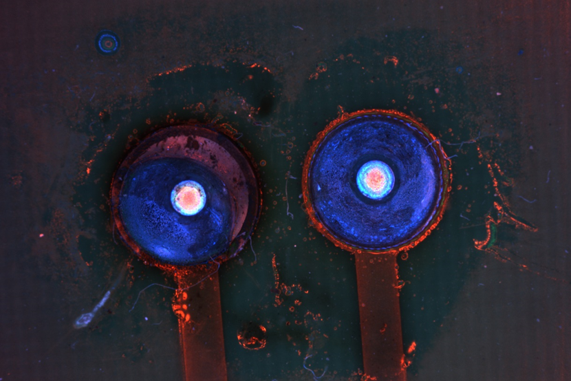
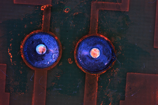
Low-angle illumination sends light across the surface rather than directly along the camera axis. Changes in solder shape, texture, and local reflectivity therefore modify the light returned to the camera. The result images show circular blue regions with red-orange edge and center responses. These colors are not universal defect codes; they are the optical response produced by the tested light, part surface, camera, and settings. Their value comes from repeatable separation between confirmed OK and NG samples, not from color alone.
How the Low-Angle RGB AIO Light Creates Useful Contrast
The tested AIO light contains concentric red, green, and blue illumination zones. Independent channel control allows engineers to adjust the spectral mix without replacing the entire light. This is useful when solder, pad finish, board coating, and contamination respond differently to each wavelength. A color industrial camera preserves these channel differences, enabling the algorithm to evaluate both brightness and color relationships. The low-angle geometry emphasizes the perimeter and surface response of the circular joint. RGB adjustment can then be used to suppress the PCB background, strengthen the blue feature region, or reveal dark spots. The correct mix must be selected with actual good and defective boards. Increasing saturation or creating dramatic colors is not the objective. The target is a stable feature set that remains separable after the light warms up, across board lots, and under controlled ambient-light conditions.
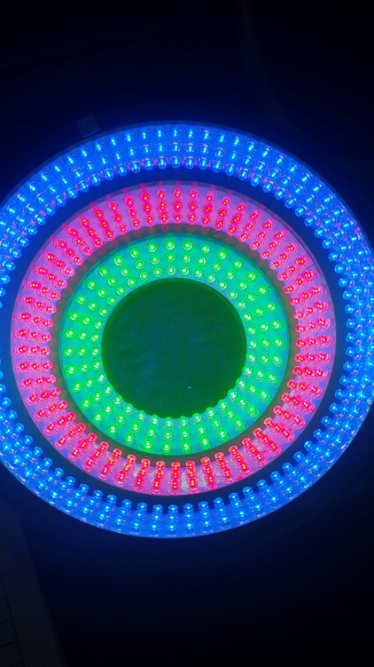
Image Features for Missing Solder, Uniform Joints, and Dark Spots
The inspection should not rely on a single average-brightness threshold. For each circular solder region, the software can measure area, circularity, diameter, edge continuity, radial intensity profile, center-to-edge brightness ratio, dark-spot area, and RGB channel ratios. A uniform OK joint should produce a repeatable distribution within limits established from confirmed samples. Missing solder may change the expected region area or eliminate part of the normal response. A dark-spot NG joint may contain a localized low-response area that breaks radial uniformity.
Segmentation should first isolate the expected solder location using the PCB geometry or a registered template. Color-space conversion can help separate chromatic information from overall brightness. The algorithm can then compare each joint with the process-specific reference rather than with an arbitrary “blue equals good” rule. If the board shifts, the registration stage must correct position before the solder features are calculated. Uncertain images should be classified for review instead of being forced into OK or NG.
Building Production Thresholds from Verified Samples
Production limits require more than the three illustrative conditions in the presentation. Collect multiple confirmed OK boards and every relevant NG type, including missing solder, insufficient solder, dark spots, contamination, flux residue, scratches, oxidation, and component-position variation. Include different PCB lots and solder-surface finishes. For each class, measure within-part and between-part variation after the machine vision light reaches thermal stability.
Lock and document the camera exposure, gain, white balance, aperture, working distance, light-to-part distance, mounting angle, and individual RGB outputs. Shield the station from ambient light or monitor ambient variation. Validation should include repeated captures, line vibration, temperature change, and planned maintenance conditions. The source presentation demonstrates visible contrast, but it does not provide accuracy, false-reject rate, cycle time, minimum defect size, or final thresholds. These values must be measured on the intended production equipment.
Engineering Takeaway and Sample-Test Requirements
This case shows why solder inspection should begin with the defect and surface response rather than with camera resolution alone. Low-angle RGB AIO lighting gives the engineer two adjustment dimensions: illumination angle and spectral composition. Together, they can reveal differences that a conventional single light may not separate. The method is promising for the tested solder geometry, but it must not be generalized to every PCB without sample testing.
For a new project, provide HIFLY with representative OK boards, every known defect type, solder and pad information, board color, required field of view, smallest defect, line speed, mounting space, and acceptance criteria. A controlled lighting test can compare RGB ratios and geometries, then document a reproducible camera, lens, light, controller, and mechanical configuration.
Send your PCB samples and solder-defect requirements to HIFLY for a controlled RGB lighting test and configuration recommendation.