EN


How to Select Machine Vision Light for Your Application
A camera can only inspect the image it receives, which is why a machine vision light is a functional part of the inspection system rather than an accessory. The right illumination makes the feature of interest separate from the background; the wrong illumination can hide a scratch, wash out a code, or make a stable part look inconsistent. Start with the defect, surface, motion, and camera geometry—not with a light shape from a catalog.
Use this process to narrow the machine vision light options before bench testing. It is especially useful when the part is reflective, curved, moving, or subject to changing ambient light.
1. Define the inspection feature before choosing a machine vision light
Write down exactly what the system must distinguish. Is it a missing component, a printed character, a raised edge, a dent, a color difference, or a surface scratch? Then define what must be suppressed: background texture, glare, shadows, oil film, or nearby features. A useful acceptance statement is: “The target feature must create enough repeatable contrast for the camera and inspection algorithm to separate it from normal variation.”
Also document the field of view, working distance, part orientation, line speed, camera exposure, lens aperture, and ambient-light conditions. These inputs prevent a common mistake: selecting a bright machine vision light that does not deliver the needed contrast at the camera.
2. Match illumination geometry to the surface and defect
Illumination angle usually matters more than raw intensity. Use these starting points, then validate them with images of good and bad parts:
- Bright-field or directional lighting: A bar light or ring light can create directional contrast for edges, texture, and features with a predictable orientation. Move the angle when glare overwhelms the feature.
- Dark-field lighting: Low-angle, grazing illumination often makes scratches, raised marks, edges, and particles stand out because those features scatter light toward the camera. It can be a strong first trial for surface-defect inspection.
- Diffuse lighting: Dome, tunnel, or other diffuse arrangements reduce the dominance of single reflections. They are useful starting options for shiny, mixed-reflectivity, or curved parts where direct lighting produces unstable hotspots.
- Backlighting: Use a backlight when the silhouette, hole, gap, outer contour, or presence/absence is the critical information. A backlight is usually not the first choice for printed surface detail.
- Coaxial lighting: For flatter reflective targets, on-axis illumination can help produce controlled returns along the optical axis and reveal selected planar markings or texture differences.
Do not treat these categories as guarantees. A polished part may need a diffuse machine vision light for one defect and a low-angle light for another. Run an A/B image test using the actual production material, finish, and defect samples.
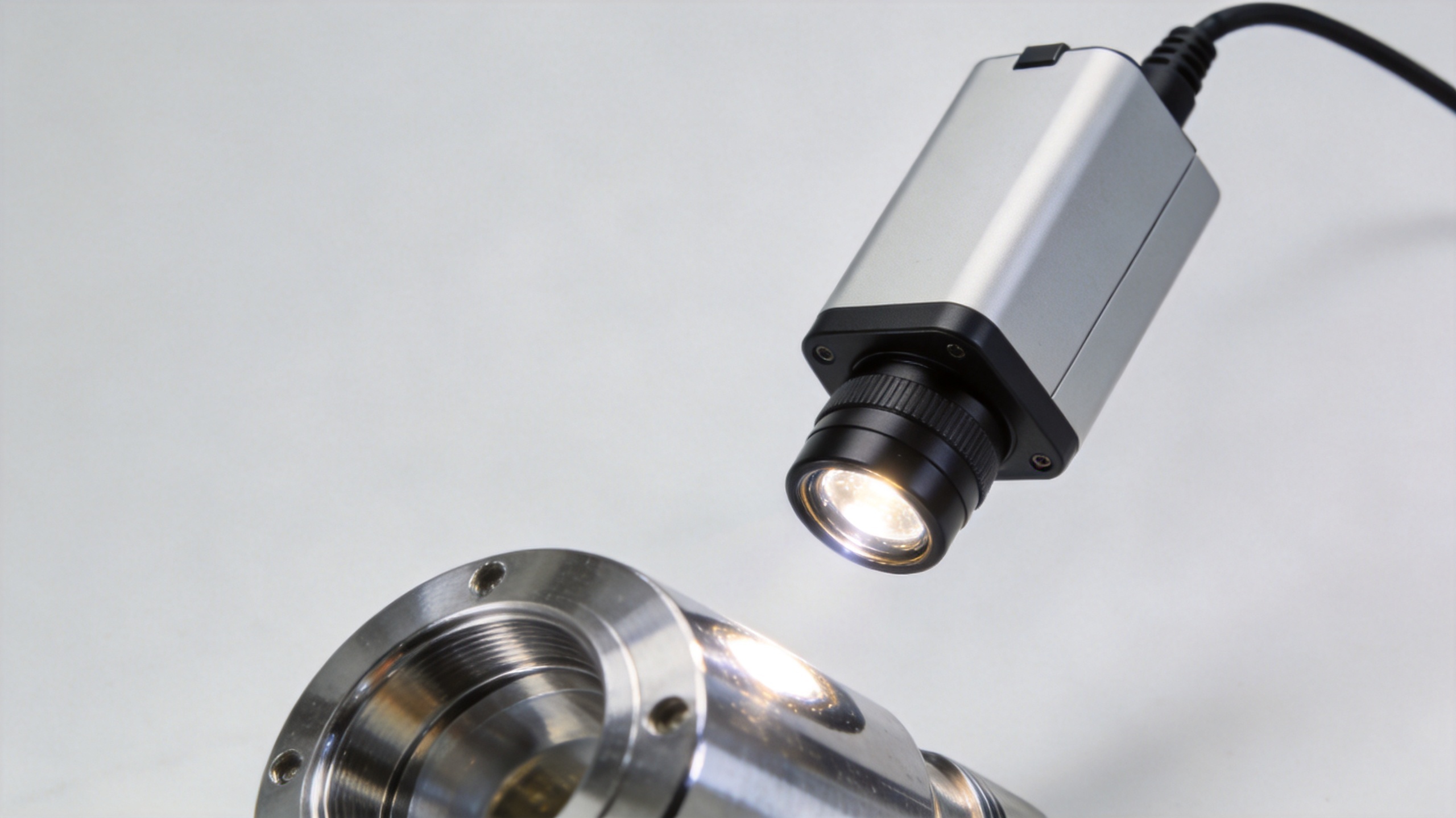
3. Select color and wavelength for image contrast
White light is a practical baseline when color must be preserved, but monochromatic illumination can simplify a grayscale inspection. The goal is not to choose a visually pleasing color; it is to create a useful difference in camera response between the feature and its surroundings.
For example, a colored label, ink, or coating may respond very differently under red, blue, green, infrared, or ultraviolet illumination. A monochrome camera with a suitable filter can further reduce unwanted spectral information. If you are considering IR or UV, verify the camera sensitivity, lens transmission, safety requirements, and the production environment before committing. HIFLY’s active variable library confirms that wavelength-specific options such as IR, UV, and narrowband visible illumination may be relevant when standard white light does not isolate the required feature.
4. Calculate coverage, uniformity, and working distance
A machine vision light must cover the field of view at the real mounting distance, not just the nominal part size. Increasing the distance can improve physical clearance, but it changes coverage and can reduce illumination at the target. Check whether the geometry creates a smooth usable area across the entire field of view, including the corners.
Evaluate uniformity with the production camera and exposure settings. An image that is acceptable in the center but dim at the edges can create threshold drift, false rejects, or extra image-processing complexity. Leave room for brackets, guarding, lens housings, and any necessary shielding from ambient light.
5. Choose continuous or strobe operation based on motion
For stationary or slow targets, continuous mode may be sufficient and straightforward. For fast conveyor motion, a strobed machine vision light synchronized to the camera exposure can deliver a short intense pulse that helps freeze motion. The light, controller, camera trigger, and exposure must be evaluated as one timing chain.
Ask the supplier for the permitted operating mode, pulse width, duty-cycle limits, trigger interface, and thermal guidance. High-current strobing is not simply “more brightness”: permissible overdrive depends on factors such as duty cycle and heat dissipation. Confirm the result over a representative production cycle, not only in a short demonstration.
6. Check controller compatibility and environmental constraints
Before release, confirm electrical compatibility between the light and controller, including input voltage, current, connector type, dimming method, trigger logic, and polarity. Check whether the controller supports the timing precision and intensity repeatability your application needs. Record a known-good setting so the system can be restored after maintenance.
Consider heat, vibration, dust, washdown, and available installation space. If the application is harsh, ask whether the selected enclosure rating and mounting arrangement are appropriate. HIFLY’s documented product-development capability and application-specific recommendation support can be useful when a standard light geometry or wavelength needs to be adapted to the inspection constraints.
7. Validate the selection with a production-like image trial
Make the final selection from the images, not from the catalog. Test normal parts, known defects, expected finish variation, and the fastest expected line speed. Compare signal-to-noise separation, glare stability, exposure margin, and false-reject behavior. Review images after the equipment has warmed up, because temperature and mounting changes can affect repeatability.
- Set the camera, lens, field of view, and working distance close to the planned installation.
- Test at least two lighting geometries when the surface is reflective or the defect is subtle.
- Try wavelength changes only where the material or mark is likely to respond differently.
- Validate continuous and strobe timing at actual production speed.
- Save representative images and the approved controller settings with the inspection specification.
A practical machine vision light selection checklist
| Question | What to verify |
|---|---|
| What must be seen? | Defect, mark, edge, color, contour, or presence/absence criterion. |
| What surface is being inspected? | Gloss, curvature, texture, transparency, and expected lot-to-lot variation. |
| Which geometry creates contrast? | Directional, dark-field, diffuse, backlight, or coaxial trial images. |
| Is the target moving? | Exposure time, motion blur, trigger timing, and strobe duty cycle. |
| Will it run reliably? | Coverage, uniformity, heat, controller compatibility, mounting, and ambient light. |
Turn the trial into a controlled comparison
Create a short test record for every machine vision light candidate. Photograph the same good and defective samples with unchanged camera settings, then score each machine vision light for feature contrast, glare, coverage, and timing margin. This makes a machine vision light decision traceable instead of subjective.
When two options look similar, change one variable at a time. Compare the machine vision light angle before changing exposure; compare wavelength before changing the inspection threshold. The selected machine vision light should still reveal the feature after normal part variation and a realistic shift in position.
Keep the approved machine vision light setup with photographs of its bracket position, controller setting, and camera recipe. That baseline helps technicians restore the system after maintenance. If a new material finish is introduced, revisit the machine vision light trial rather than assuming the existing setting will remain robust.
For multi-station inspection, ensure each machine vision light has a defined role. One machine vision light may reveal a surface scratch while another provides the silhouette measurement. Separating these jobs can produce more dependable images than asking a single machine vision light to reveal every feature.
Final takeaway
Selecting a machine vision light is a contrast-engineering task. Start with the feature you need to reveal, use illumination geometry to manage reflections and shadows, then confirm wavelength, coverage, timing, and thermal limits with real images. A structured trial reduces the chance of solving a software problem that is actually caused by lighting. For applications with unusual surfaces, speeds, or wavelengths, engage a lighting specialist early and bring representative parts and defect samples to the discussion.