EN
EN


Top 5 geometry mistakes when selecting machine vision lights and how to fix them quickly.
Selecting the right machine vision lights is one of the most critical decisions in industrial imaging systems, yet geometry mistakes during the selection process remain surprisingly common across manufacturing facilities. These errors directly impact image quality, reduce inspection accuracy, and ultimately waste time and resources on rework or failed quality checks. Understanding the most frequent geometry mistakes when selecting machine vision lights can help engineers and technicians avoid costly installation failures and optimize their vision systems from the start.
When implementing machine vision lights in your production line, geometry mistakes often stem from inadequate planning, incomplete understanding of optical principles, or failure to account for the specific characteristics of your inspection target. This guide walks through the five most damaging geometry mistakes and provides actionable solutions to fix them quickly, ensuring your machine vision lights deliver consistent, reliable illumination that supports accurate defect detection and dimensional measurement.
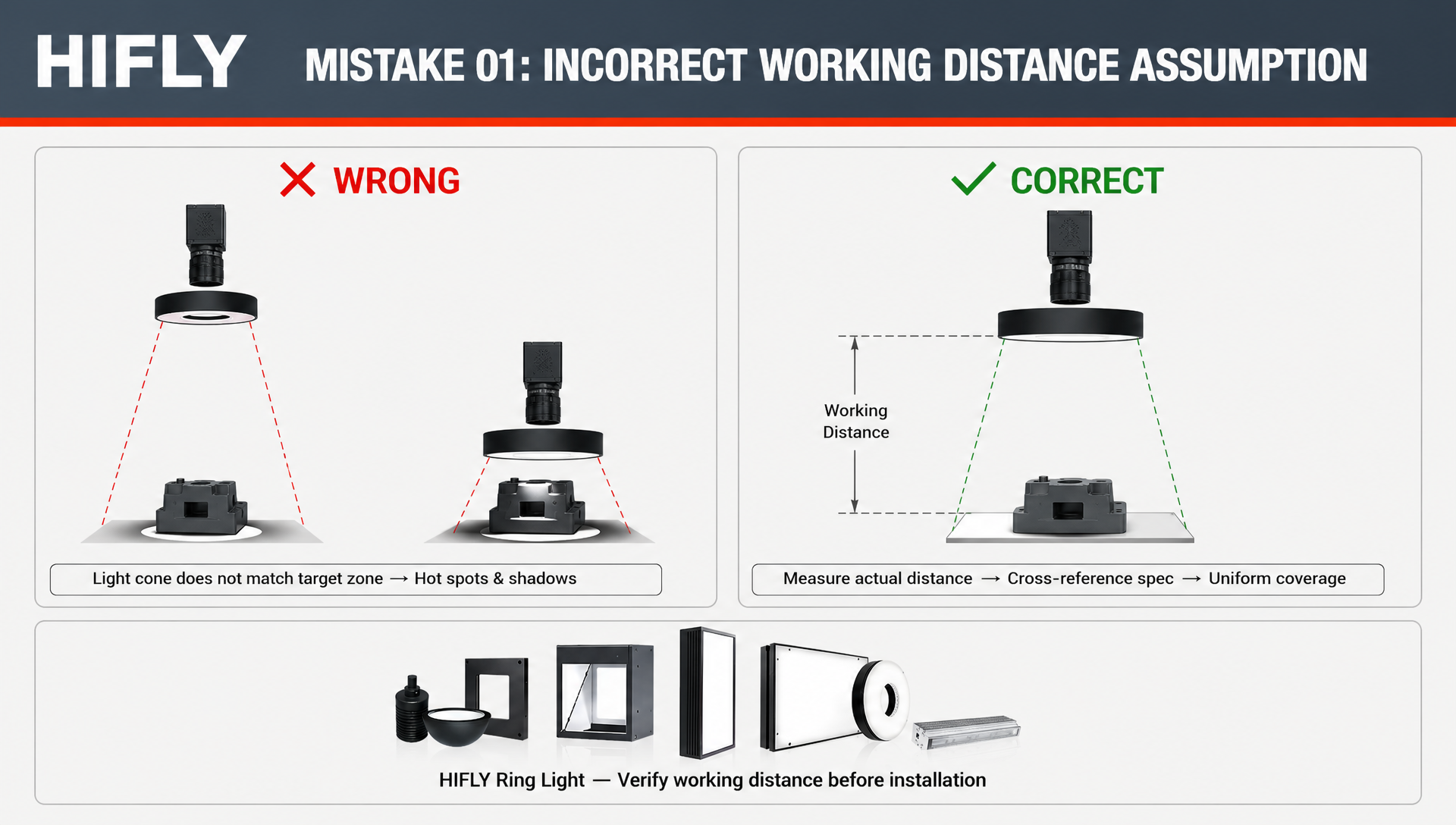
Incorrect Working Distance Assumption
Understanding Working Distance in Machine Vision Lights
Working distance is the physical gap between the lens and the target surface where machine vision lights must deliver optimal illumination. Many engineers select machine vision lights without carefully measuring or confirming this critical dimension, leading to poor light distribution and wasted optical performance. When working distance is miscalculated, the intensity profile of machine vision lights does not align with the target area, creating hot spots, shadows, or insufficient brightness in key inspection zones.
To fix this geometry mistake with your machine vision lights, measure the actual distance from your camera lens to the target surface before finalizing any lighting configuration. Document this measurement precisely, then cross-reference it against the machine vision lights manufacturer specifications to ensure the lighting geometry is matched correctly. This simple verification prevents installation surprises and ensures machine vision lights illuminate the inspection area uniformly.
Optimizing Lighting Geometry for Your Setup
Different machine vision lights designs, such as ring lights, coaxial lights, and spot lights, each have optimal working distance ranges where their geometry delivers peak performance. If your working distance falls outside the recommended range for your chosen machine vision lights, the illumination pattern deteriorates, making defect detection unreliable. Adjust your setup by either repositioning the camera and light assembly or selecting a different machine vision lights design that matches your physical constraints.
Advanced machine vision lights can be customized with adjustable apertures and beam angles to extend usable working distance windows. This flexibility makes geometry adaptation faster and reduces the need for complete system redesign when spatial limitations constrain where machine vision lights can be mounted.
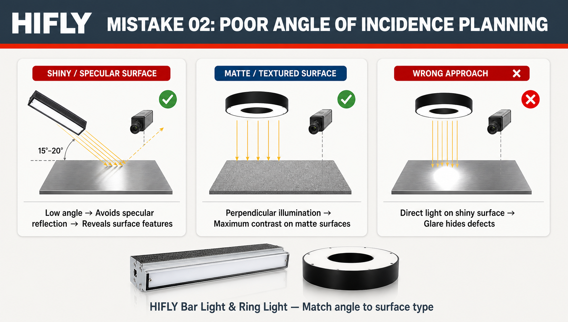
Poor Angle of Incidence Planning
Why Angle Matters for Machine Vision Lights
The angle of incidence is the angle at which light rays from your machine vision lights strike the target surface, and it profoundly affects how surface features appear in captured images. Inexperienced system designers often fail to account for how different angles of machine vision lights interact with surface geometry, material reflectivity, and feature orientation. When the angle of incidence is poorly chosen, shiny surfaces reflect light away from the camera, dull surfaces appear flat and featureless, and raised or recessed features become invisible.
To correct this geometry mistake with machine vision lights, analyze the target surface characteristics and the specific features you must inspect. Shiny or reflective materials require more oblique angles where machine vision lights approach at shallow angles, reducing specular reflection. Conversely, matte or textured surfaces often benefit from more direct illumination where machine vision lights strike nearly perpendicular to the surface, maximizing contrast and detail visibility.
Implementing Angle Adjustments
Many advanced machine vision lights designs include adjustable mounting brackets or tiltable light heads that allow rapid angle experimentation without replacing hardware. Start with a 45-degree angle as a baseline for machine vision lights, then gradually shift the angle while observing live images to find the sweet spot where target features show maximum contrast and clarity. Ring-style machine vision lights naturally create diffuse, nearly perpendicular illumination, making them ideal for general-purpose work, while directional machine vision lights offer more precise angle control for specialized applications.
Documenting the final angle geometry you select for your machine vision lights ensures consistency during maintenance, recalibration, or system expansion. This simple practice prevents angle drift and maintains stable image quality across production runs.
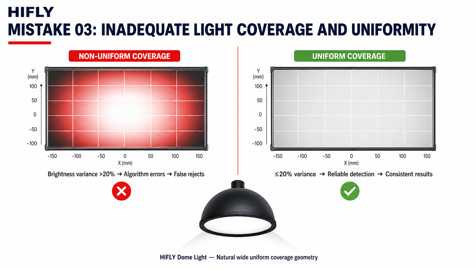
Inadequate Light Coverage and Uniformity
Identifying Coverage Gaps in Machine Vision Lights
Coverage refers to how completely machine vision lights illuminate the entire target area, while uniformity describes how evenly that light is distributed across the field. Geometry mistakes in coverage planning create dark zones, unlit corners, or inconsistent brightness that confuses image analysis algorithms and causes inspection failures. Many engineers select machine vision lights based solely on total brightness output without accounting for the geometric spread or focus characteristics that determine actual coverage on the target surface.
To diagnose coverage problems with your machine vision lights, capture test images across the entire inspection area and analyze brightness levels at the center, edges, and corners. If brightness varies by more than 20 percent across the target zone, your machine vision lights geometry requires adjustment. This might involve adding secondary light sources, adjusting the primary machine vision lights position, or switching to a light design with naturally more uniform beam spread.
Achieving Uniform Illumination
Coaxial and dome-style machine vision lights excel at delivering uniform coverage because their geometric design naturally spreads light across a wide area with minimal focus. In contrast, spot lights and focused LED machine vision lights concentrate intensity in smaller regions, making them prone to coverage geometry mistakes when applied to large inspection zones. If your target area is wider than your current machine vision lights can uniformly illuminate, either reduce the inspection field of view or upgrade to a machine vision lights design engineered for broader geometric coverage.
Diffusers and light-shaping optics embedded in modern machine vision lights modify beam geometry to improve uniformity and reduce hot spots. These optical components redistribute light energy evenly across the illumination pattern, solving many geometry mistakes related to uneven brightness without requiring repositioning or hardware changes.
Misalignment Between Light and Camera Optics
Optical Axis Alignment Basics
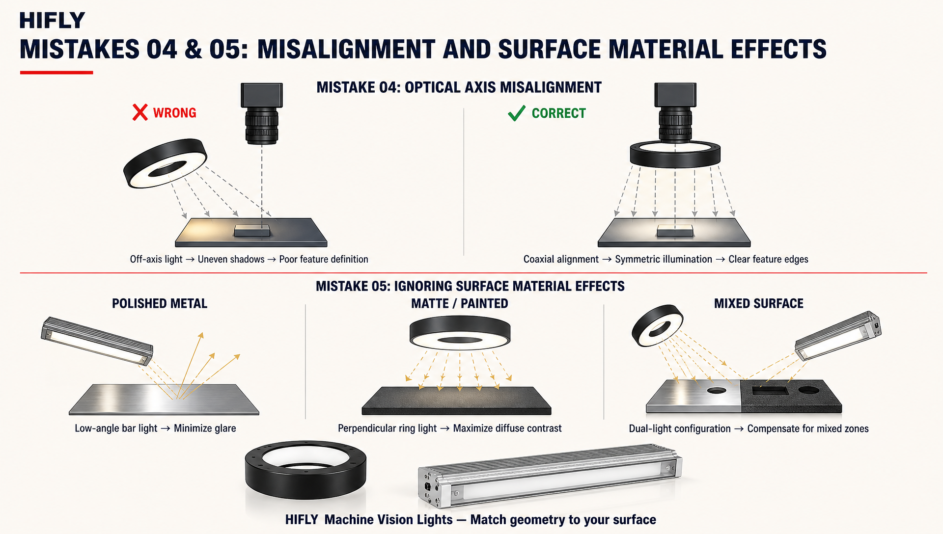
The optical axis is an imaginary line representing the primary viewing direction of your camera lens and the primary illumination direction of your machine vision lights. When geometry mistakes cause misalignment between the camera optical axis and the machine vision lights beam, the captured images show uneven illumination, unnatural shadows, and poor feature definition. This is especially problematic when using coaxial or semi-coaxial machine vision lights designs, where optical axis alignment is essential for the system to function correctly.
Fixing this geometry mistake requires careful setup and verification using a test target or alignment reference. Position your machine vision lights so that the beam centerline coincides with the camera lens optical axis within a few millimeters. Use test images to confirm symmetrical illumination; if the target appears brighter on one side, rotate or shift the machine vision lights until symmetry is restored.
Using Alignment Tools
Precision mounting plates, optical benches, and adjustable light holders help prevent alignment geometry mistakes when installing machine vision lights. Many professional vision system builders use laser alignment jigs to confirm that machine vision lights beam direction and camera viewing direction are coaxial before final installation. This upfront investment in proper geometry setup prevents misalignment-related image quality problems and reduces troubleshooting time.
After alignment, document the position of every component in your machine vision lights mounting system. Detailed setup notes and photographs protect against accidental geometric shifts during maintenance or when team members service the equipment later.
Neglecting Surface Texture and Material Effects
How Surface Properties Interact with Machine Vision Lights
Surface texture and material reflectivity create complex interactions with machine vision lights that many geometry-selection decisions overlook. Shiny metallic surfaces reflect machine vision lights in specular patterns, creating bright glare spots that obscure defects, while rough or matte surfaces scatter light diffusely, potentially hiding fine texture details or micro-defects. The geometry mistake here is selecting and positioning machine vision lights without understanding how your specific target material will respond to the light distribution pattern.
Analyze your target material before finalizing machine vision lights selection and positioning. If inspecting polished steel or aluminum, you must use low-angle geometry where machine vision lights approach at acute angles relative to the surface normal, minimizing direct specular reflection into the camera. For matte or painted surfaces, more perpendicular geometry from machine vision lights often works well because specular reflection is already minimal, allowing diffuse light to reveal surface features clearly.
Quick Fixes for Material-Related Geometry Mistakes
Polarizing filters or anti-glare coatings can modify how captured light interacts with your camera sensor, reducing the negative effects of material-related geometry mistakes in machine vision lights positioning. Additionally, using multiple machine vision lights sources at different angles creates more complex illumination geometry that compensates for material properties you cannot change. If your target is shiny on one inspection zone and textured on another, dual-light configurations allow each machine vision lights source to optimize geometry for its respective zone.
Testing with a physical prototype before committing to permanent machine vision lights installation is the most reliable way to catch material-related geometry mistakes. Set up a temporary test configuration, inspect sample parts using live camera feedback, and adjust the geometry until images consistently show the defects or features you need to detect reliably.
FAQ
What is the most common geometry mistake when selecting machine vision lights?
The most common geometry mistake is inadequate planning for working distance. Engineers often choose machine vision lights without confirming the physical distance from the camera lens to the target surface, resulting in illumination patterns that do not align with the inspection zone. This simple oversight cascades into poor image quality and unreliable inspection performance. Always measure working distance precisely before purchasing or configuring machine vision lights.
How can I quickly test whether my machine vision lights geometry is correct?
Capture live images from your camera with sample parts positioned in the inspection zone and evaluate whether illumination is uniform, whether all target features are visible, and whether brightness is adequate across the entire field of view. Use image analysis software to measure brightness variance across different image regions; if variation exceeds 20 percent, geometry adjustment is needed. Adjust machine vision lights position, angle, or configuration incrementally and re-test until images show consistent, balanced illumination with clear feature visibility.
Can geometry mistakes with machine vision lights be fixed after installation?
Yes, many geometry mistakes can be corrected through machine vision lights repositioning, angle adjustment, or mounting modifications without full system replacement. However, some errors, such as selecting the wrong light type entirely for your working distance, may require upgrading to a different machine vision lights design. Preventive geometry planning during system design is always more cost-effective than fixing mistakes after installation is complete.