EN
EN


How to synchronize multiple machine vision cameras for stereo 3D measurement applications?
Synchronizing multiple machine vision cameras for stereo 3D measurement is one of the most technically demanding challenges in modern industrial imaging. When machine vision cameras capture the same scene at slightly different moments, stereo disparity calculations become unreliable, leading to dimensional errors and failed inspections. Getting synchronization right from the start is essential for any stereo 3D measurement system that demands consistent, high-accuracy results.
This guide explains the key methods and best practices engineers use to synchronize machine vision cameras in stereo 3D measurement setups. Whether you are working with two machine vision cameras in a simple stereo pair or managing a multi-camera array, understanding hardware triggers, software synchronization, and calibration workflows will help you build a robust and precise 3D measurement solution. Every decision you make about how machine vision cameras communicate and fire together directly impacts measurement accuracy and system reliability.
Hardware Trigger Methods for Synchronizing Machine Vision Cameras
External Trigger Signals and Timing Control
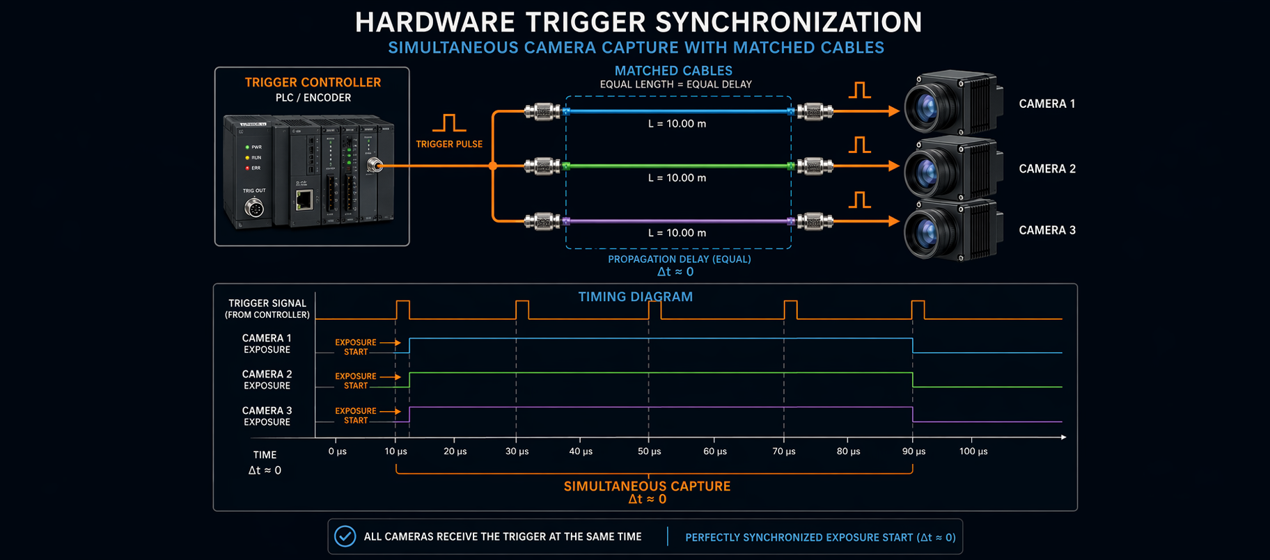
The most reliable way to synchronize machine vision cameras in stereo 3D applications is through external hardware triggers. In this approach, a dedicated trigger source, such as a PLC, encoder, or dedicated trigger controller, sends a simultaneous electrical signal to all machine vision cameras in the array. When machine vision cameras receive the same trigger pulse at the same moment, their image sensors begin exposure at identical times, eliminating temporal offset between frames. For high-speed or moving-object inspections, hardware-triggered machine vision cameras are the industry-standard solution because they remove the latency and jitter that software-based methods introduce.
Proper cabling is critical when using hardware triggers with machine vision cameras. Each camera in the stereo pair or array should receive the trigger signal through matched-length cables to minimize propagation delay differences. Even small timing differences between machine vision cameras can introduce sub-pixel errors in stereo reconstruction. Industrial-grade trigger controllers designed specifically for machine vision cameras offer configurable pulse widths, delays, and repeat rates, giving engineers fine-grained control over multi-camera synchronization.
Genlock and Frame Synchronization Standards
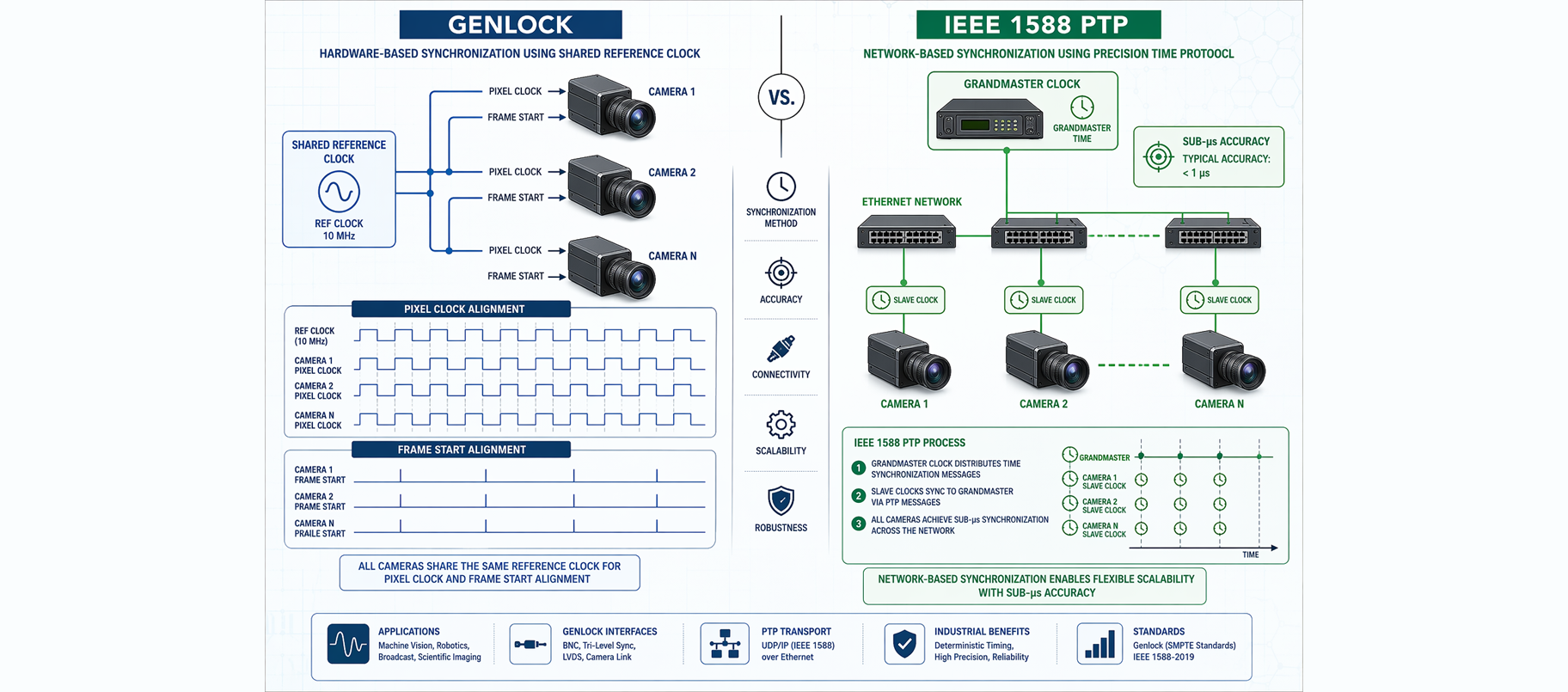
Some machine vision cameras support Genlock or IEEE 1588 Precision Time Protocol (PTP), which are advanced synchronization standards used in multi-camera setups. Genlock aligns the pixel clock and frame start signals of multiple machine vision cameras to a shared reference, ensuring all sensors capture frames at exactly the same phase. IEEE 1588 PTP allows machine vision cameras connected over a standard Ethernet network to synchronize their internal clocks to sub-microsecond accuracy. These features are especially valuable when machine vision cameras are spread across a large factory floor or cannot easily be connected by direct trigger wiring. Choosing machine vision cameras that natively support these standards simplifies integration and improves long-term synchronization stability.
Software Synchronization Strategies for Machine Vision Cameras
Host-Side Timestamp Matching and Buffering
When hardware trigger options are limited, engineers can use host-side software synchronization to match frames from multiple machine vision cameras. In this method, each camera embeds a precise timestamp into its image data, and the host computer collects frames from all machine vision cameras into a buffer. The software then selects matched frame sets based on timestamp proximity, discarding frames where the timing gap between machine vision cameras exceeds a defined threshold. While this approach is more flexible and easier to deploy in systems using existing machine vision cameras, it introduces a small latency penalty. Software-based synchronization works best in relatively static scenes or applications where objects move slowly enough that a few milliseconds of timing difference between machine vision cameras does not materially affect 3D reconstruction quality.
Streaming Protocols and Bandwidth Management
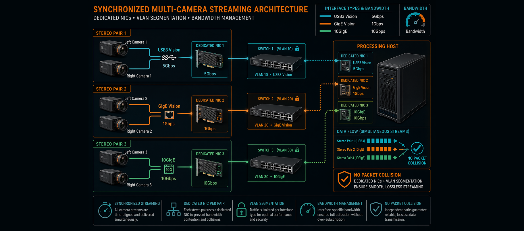
Synchronized machine vision cameras generate high volumes of simultaneous image data that must be transferred without bottlenecking. USB3 Vision and GigE Vision are the most common interface standards used with industrial machine vision cameras, and both support simultaneous streaming from multiple devices. When deploying stereo machine vision cameras over GigE, assigning each pair of machine vision cameras to dedicated network interfaces prevents packet collisions and ensures consistent frame delivery. For high-resolution machine vision cameras running at high frame rates, 10GigE interfaces or Camera Link HS may be necessary. Proper network architecture planning ensures that synchronized machine vision cameras deliver frames to the processing host without introducing artificial timing jitter from network congestion.
Calibration and Alignment of Synchronized Machine Vision Cameras
Stereo Calibration Procedures
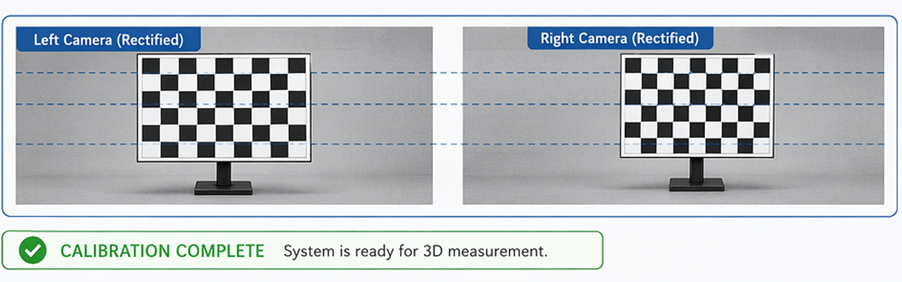
Synchronizing machine vision cameras at the hardware or software level is only half the work. Stereo 3D measurement also requires precise geometric calibration of the machine vision cameras relative to each other. A standard stereo calibration procedure involves capturing a flat checkerboard target from multiple angles with all machine vision cameras firing simultaneously. Calibration software extracts corner points from these synchronized images and computes intrinsic parameters, such as focal length and distortion coefficients, for each of the machine vision cameras, as well as the extrinsic rotation and translation between them. Without this calibration step, even perfectly synchronized machine vision cameras will produce 3D point clouds that are geometrically distorted or scaled incorrectly.
Maintaining Calibration Stability Over Time
Industrial deployments of stereo machine vision cameras are subject to vibration, thermal expansion, and mechanical drift that can shift the relative alignment of machine vision cameras over time. Engineers should establish a regular recalibration schedule and monitor stereo reconstruction error metrics to detect drift early. Fixed mounting brackets with anti-vibration isolators help machine vision cameras maintain their calibrated positions during continuous operation. Some advanced machine vision cameras include onboard IMU sensors or mechanical reference targets that allow automated self-calibration routines to run periodically without halting production. Keeping machine vision cameras well calibrated ensures that synchronization precision translates directly into accurate, repeatable 3D measurements over the system's operational lifetime.
FAQ
What is the minimum number of machine vision cameras needed for stereo 3D measurement?
A stereo 3D measurement system requires at least two machine vision cameras positioned at a known baseline distance apart. Two synchronized machine vision cameras provide sufficient disparity information for 3D reconstruction. Adding more machine vision cameras to the array can improve depth coverage, reduce occlusions, and increase measurement robustness in complex scenes.
Can machine vision cameras with different resolutions be synchronized for stereo use?
While it is technically possible to synchronize machine vision cameras with different resolutions using hardware triggers or PTP, mixed-resolution stereo pairs introduce significant calibration and rectification complexity. For best results, stereo machine vision cameras should share the same sensor size, resolution, and lens specifications. Mismatched machine vision cameras often require custom software to handle resolution scaling before stereo matching algorithms can be applied effectively.
How does ambient temperature affect synchronized machine vision cameras in 3D measurement?
Temperature changes can cause thermal expansion in the mounting structures holding machine vision cameras, gradually shifting their relative positions and invalidating stereo calibration. Machine vision cameras used in environments with large temperature swings should be mounted on thermally stable materials and recalibrated more frequently. Some industrial machine vision cameras include thermal compensation features that adjust internal parameters automatically, helping maintain measurement accuracy without manual intervention.