EN
EN


What resolution is ideal for a machine vision camera inspecting 0201 resistors on PCBs?
Inspecting 0201 resistors on a printed circuit board is one of the most demanding tasks a machine vision camera can face in electronics manufacturing. These miniature components measure just 0.6 mm by 0.3 mm, meaning that any machine vision camera deployed for this job must deliver extraordinary pixel-level resolution to detect placement errors, solder bridges, and missing parts with confidence. Choosing the wrong resolution is not simply a matter of image sharpness — it directly affects yield rates, inspection speed, and production reliability.
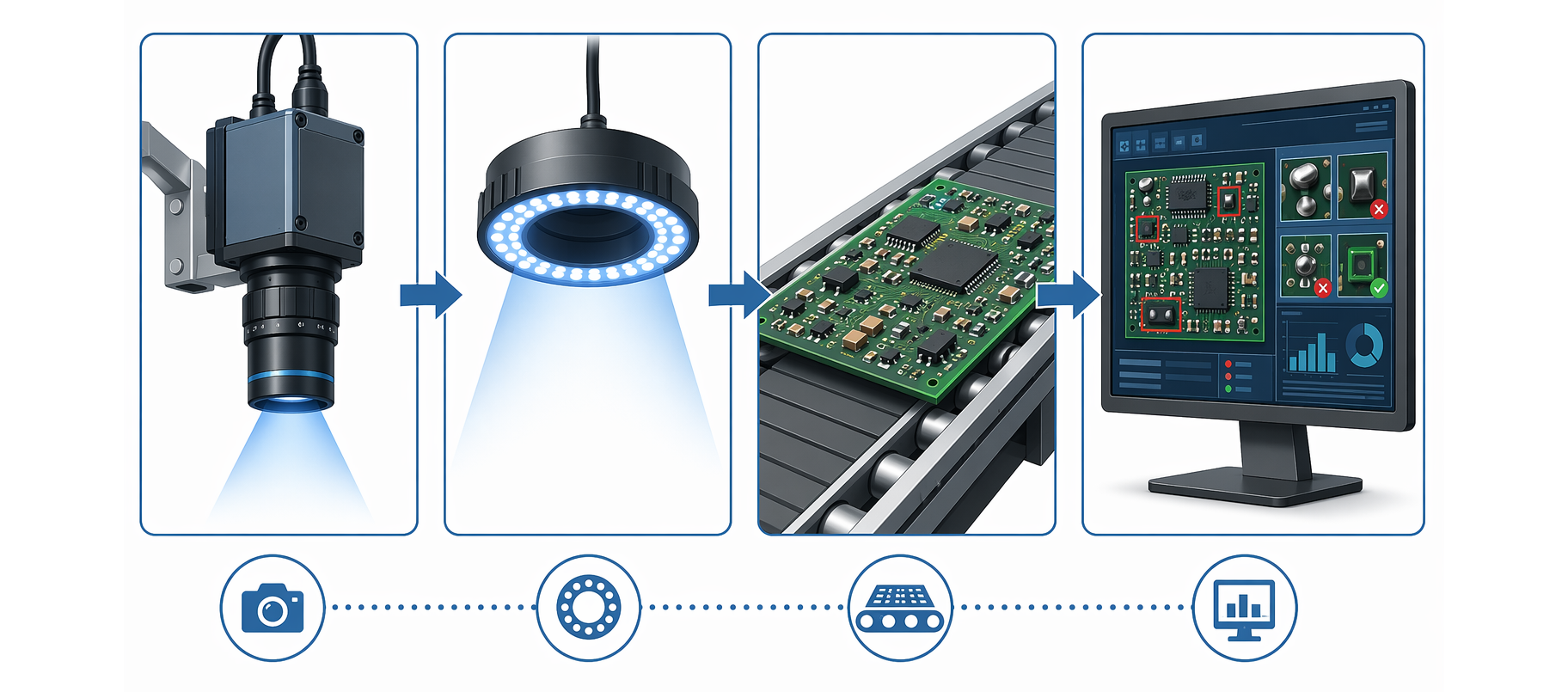
This article explains the resolution requirements that a machine vision camera must meet when inspecting 0201 components, how to calculate the minimum pixel budget needed, and what optical and sensor factors influence the final imaging outcome. Whether you are designing an automated optical inspection system from scratch or upgrading an existing line, understanding the relationship between component size, field of view, and machine vision camera resolution is essential for making a sound technical decision.
Understanding the Resolution Demands of 0201 Inspection
Why Component Size Dictates Camera Resolution
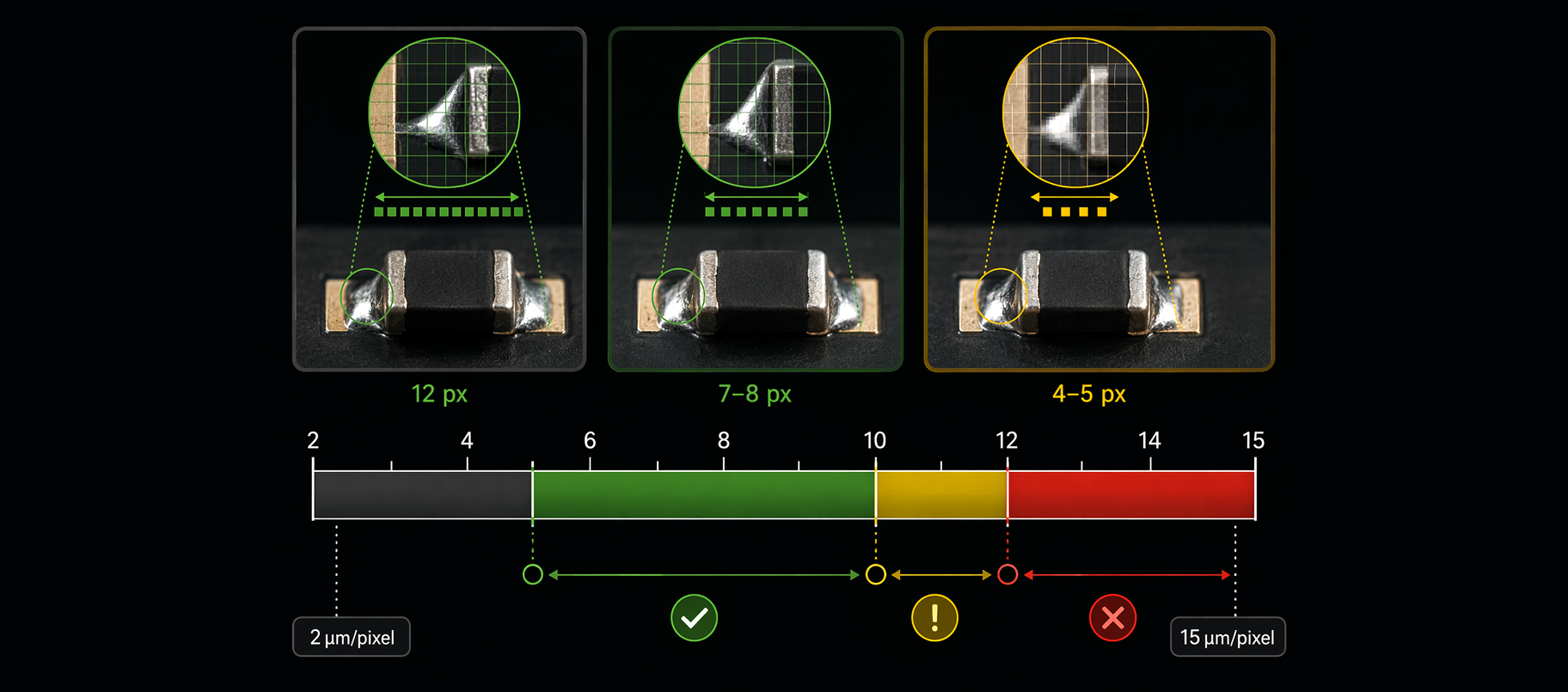
A 0201 resistor measures 0.6 mm in length and 0.3 mm in width. For a machine vision camera to reliably detect defects on such a component, the general rule in machine vision is that at least 5 to 10 pixels must cover the smallest feature of interest. If the critical feature is the solder fillet or the component pad, which can be as narrow as 0.1 mm, a machine vision camera must achieve a pixel resolution of roughly 10 microns per pixel or better. This is a significantly tighter requirement than what is needed for 0402 or 0603 components, which have larger contact areas and more tolerant placement windows.
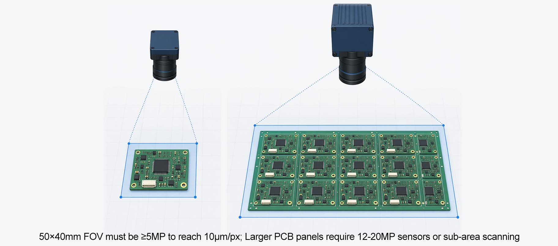
The machine vision camera resolution you select also depends on your field of view. A machine vision camera covering a 50 mm by 40 mm area would need at least a 5-megapixel sensor to achieve 10 microns per pixel. For a larger PCB panel, the same machine vision camera would either need to work in a tiled scan mode or use a higher-resolution sensor, such as a 12-megapixel or 20-megapixel model. In practice, many machine vision camera systems designed for 0201 inspection use sensors in the 9 to 20 megapixel range to balance coverage area with the required spatial detail.
Pixel Budget Calculation for Small Component Inspection
The pixel budget calculation is a foundational step when specifying a machine vision camera for 0201 work. Start with the field of view width, divide it by the sensor pixel count in that axis, and the result is the ground sampling distance or pixel pitch at the object plane. A machine vision camera with a 10,000-pixel horizontal sensor covering a 100 mm wide field produces 10 microns per pixel — exactly at the lower boundary of acceptable resolution for 0201 inspection. Reducing the field of view to 60 mm with the same machine vision camera drops the resolution to 6 microns per pixel, which provides a stronger safety margin for defect detection. Engineers evaluating a machine vision camera for this application should always calculate the pixel budget before committing to a sensor size or lens combination.
Key Sensor and Optical Factors That Shape Inspection Quality
Sensor Format and Pixel Size in a Machine Vision Camera
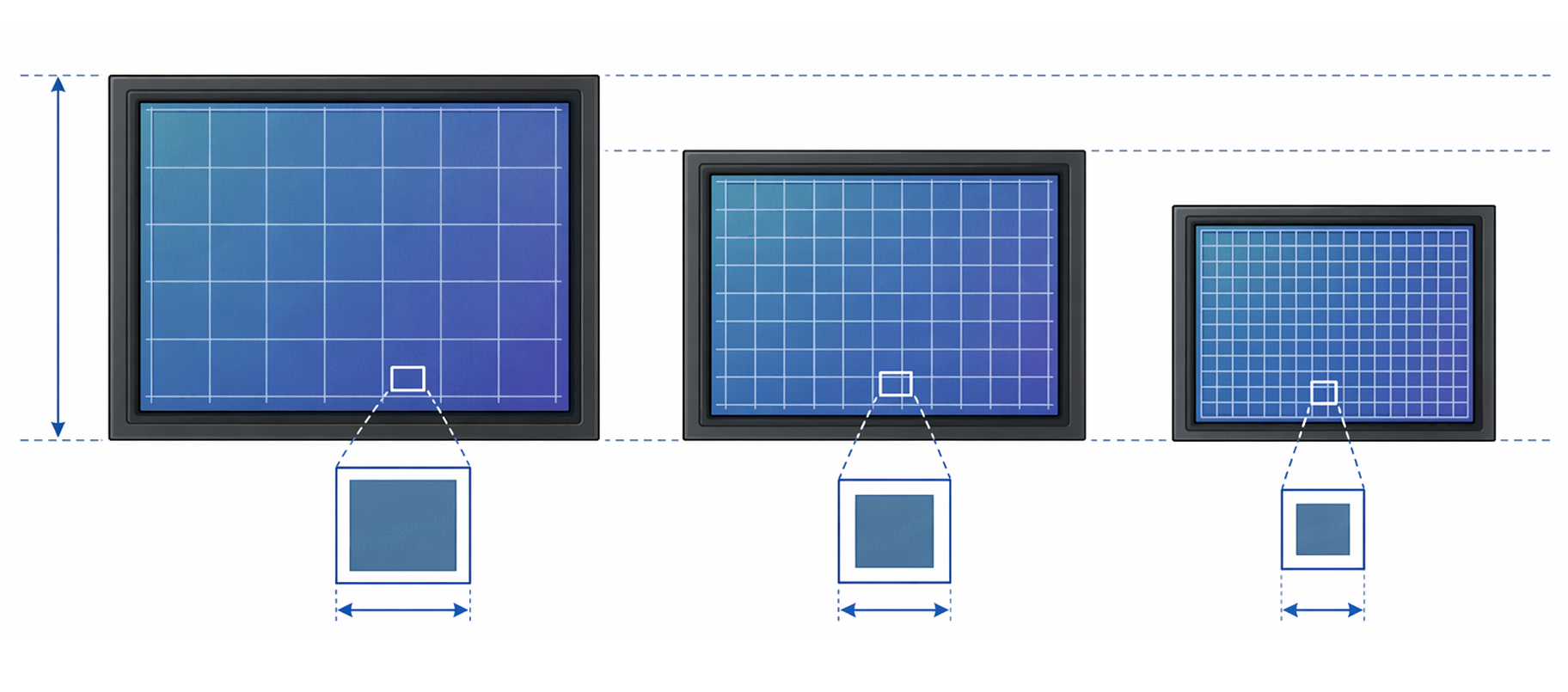
Beyond raw megapixel count, the physical pixel size inside a machine vision camera plays a major role in image quality. Smaller pixels — typically 2.4 to 3.45 microns — allow a machine vision camera to pack more resolution into a compact sensor format, but they also reduce the light collected per pixel. For 0201 inspection under bright structured lighting, this trade-off is usually acceptable because illumination can be controlled precisely. A machine vision camera with a 1-inch or larger sensor format generally delivers better signal-to-noise performance and supports higher magnification optics without vignetting. When reviewing machine vision camera specifications, always check both the pixel size and the sensor format together rather than evaluating megapixels alone.
Lens Selection and Its Impact on Effective Resolution
A machine vision camera is only as effective as the lens mounted to it. Even a 20-megapixel machine vision camera will underperform if paired with a low-grade lens that introduces chromatic aberration or field curvature. For 0201 PCB inspection, telecentric lenses are strongly preferred because they eliminate perspective distortion and provide uniform magnification across the entire field. A well-matched telecentric lens ensures that the machine vision camera captures accurate dimensional data at the edges of the image, not just at the center. The lens should be capable of resolving features at the same spatial frequency that the machine vision camera sensor demands, typically expressed in line pairs per millimeter.
Practical Resolution Guidelines for 0201 PCB Lines
Recommended Resolution Range for Production Use
Based on the pixel budget logic and the physical size of 0201 components, a machine vision camera intended for this inspection task should target a ground sampling resolution between 5 and 10 microns per pixel at the object plane. At 5 microns per pixel, a machine vision camera provides a generous pixel coverage of 12 pixels across the 0.06 mm solder fillet, offering high confidence in defect detection. At 10 microns per pixel, the machine vision camera still achieves the minimum 5-pixel coverage needed for reliable classification. Going below 10 microns per pixel with a machine vision camera is generally not recommended for automated optical inspection of 0201 components because it introduces too much ambiguity at the defect classification stage.
Balancing Resolution Against Throughput
Higher resolution in a machine vision camera always comes with trade-offs in speed and data throughput. A machine vision camera producing 20-megapixel images at 30 frames per second generates a significant data stream that requires fast interface standards such as USB 3.0, GigE, or CoaXPress. Machine vision camera systems for high-throughput PCB lines must account for image transfer latency, processing time, and storage requirements alongside pixel resolution. In multi-camera AOI systems, each machine vision camera may be assigned a smaller zone of the board, allowing lower per-camera resolution while collectively maintaining full-board inspection coverage at speed. System architects must treat the machine vision camera as one component in a larger imaging pipeline rather than an isolated specification choice.
FAQ
What is the minimum megapixel count for a machine vision camera inspecting 0201 resistors?
A machine vision camera covering a standard 50 mm by 40 mm field of view needs at least 5 megapixels to reach 10 microns per pixel resolution. For tighter pixel budgets or larger fields, a 12 to 20 megapixel machine vision camera is more appropriate and provides a greater margin for reliable defect detection on 0201 components.
Can a machine vision camera with a rolling shutter be used for 0201 inspection?
A global shutter machine vision camera is strongly preferred for 0201 PCB inspection because it captures the entire image at one instant, eliminating motion blur when the board or camera moves during scanning. A rolling shutter machine vision camera may introduce distortion artifacts at inspection speeds common in high-volume SMT production environments, which can cause false failures or missed defects.
How does lighting affect the effective resolution of a machine vision camera for this task?
Lighting directly influences how well a machine vision camera can resolve fine solder features on 0201 components. Insufficient or poorly directed light reduces contrast, making it harder for the machine vision camera to distinguish component edges from the PCB substrate. Structured lighting, such as ring lights or coaxial illumination, maximizes contrast and allows the machine vision camera to operate at its full optical resolution, ensuring that pixel-level detail translates into reliable inspection results.