EN
EN


Step by step guide for machine vision light controller?
A machine vision light controller is a critical component in any industrial inspection system, responsible for managing the intensity, timing, and behavior of lighting sources that illuminate objects during machine vision image capture. Proper configuration of a machine vision light controller directly impacts image quality, defect detection accuracy, and overall system reliability. Without a well-tuned machine vision light controller, even the most advanced camera sensors and software algorithms will struggle to deliver consistent, high-quality images for reliable quality control and defect detection across manufacturing environments.
Setting up and configuring a machine vision light controller requires understanding hardware connections, software settings, lighting physics, and application-specific optimization techniques. This comprehensive guide walks you through the essential steps to install, configure, and optimize your machine vision light controller for maximum performance in industrial machine vision applications.
Understanding the Hardware Foundation of Your Machine Vision Light Controller
Key Components and Electrical Connections
A typical machine vision light controller integrates multiple hardware elements that work together to manage lighting output. The machine vision light controller contains power supply circuits, relay modules, current regulation components, and communication interfaces that allow it to receive commands from your camera system or vision software. The first critical step is properly identifying all connector types on your machine vision light controller, including power input terminals, light output channels, trigger signal inputs, and communication ports such as USB, Ethernet, or serial RS-232.
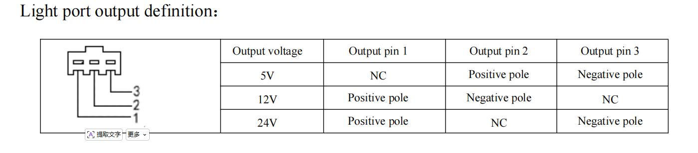
Before powering on your machine vision light controller, verify that all electrical connections match the manufacturer's wiring diagram precisely. Each channel of the machine vision light controller should be clearly labeled for the specific lights it will control, whether those are LED ring lights, bar lights, backlight panels, or directional spot lights. Double-check voltage specifications for both the machine vision light controller power supply and each individual light source to prevent equipment damage or safety hazards.
Communication Protocol Configuration
Your machine vision light controller must be configured to communicate with your imaging system using the appropriate protocol. Most modern machine vision light controller units support multiple communication standards including GPIO digital signals, Ethernet-based protocols, or dedicated machine vision interfaces. Identify which communication method your machine vision light controller will use, then install required drivers and communication libraries on your vision system computer.
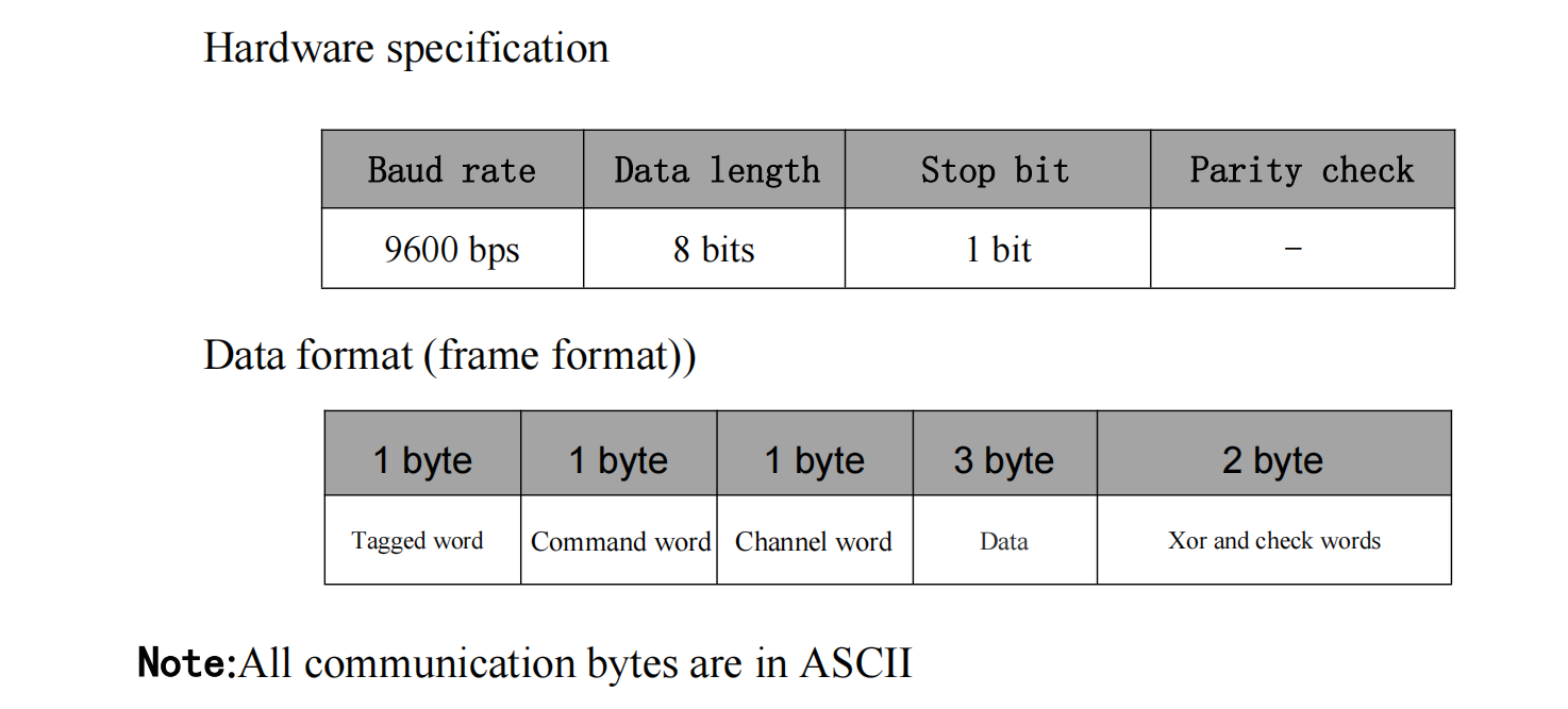
Setting up the communication pathway between your camera or vision software and the machine vision light controller ensures that lighting commands are transmitted reliably and with minimal latency. Test the connection before proceeding with full system integration by sending basic commands to verify that your machine vision light controller receives and responds to signals correctly.
Channel Configuration and Light Output Optimization
Mapping Light Sources to Controller Channels
Each output channel on your machine vision light controller must be individually configured and mapped to its corresponding light source. Begin by assigning descriptive names to each channel on your machine vision light controller such as 'top ring light,' 'back panel,' or 'side directional light' so your team can quickly understand which physical light each machine vision light controller channel controls during troubleshooting and optimization.
Next, establish the current output range for each channel. Your machine vision light controller typically offers selectable current levels, often ranging from 10% to 100% maximum output. Configure each channel's default intensity based on the light source specifications and your initial inspection requirements. A properly configured machine vision light controller allows you to set independent power levels for each light, enabling sophisticated multi-light setups that create optimal illumination angles and contrast for accurate object detection.
Brightness and Synchronization Settings
The machine vision light controller brightness adjustment feature allows real-time or preset intensity control, which is essential for adapting to changing ambient conditions or different product types on your production line. Most modern machine vision light controller models offer pulse-width modulation or direct analog control to fine-tune light intensity without generating excessive heat in the system.
Synchronization between your machine vision light controller and camera shutter is critical for consistent image acquisition. Configure your machine vision light controller to trigger light output precisely when the camera sensor is active, minimizing wasted power consumption and reducing thermal stress on LED light sources. Many advanced machine vision light controller units support precise millisecond-level timing adjustment and can store multiple preset lighting profiles for different product inspection scenarios.
Testing, Calibration, and Troubleshooting Your Machine Vision Light Controller
Initial System Testing and Image Validation
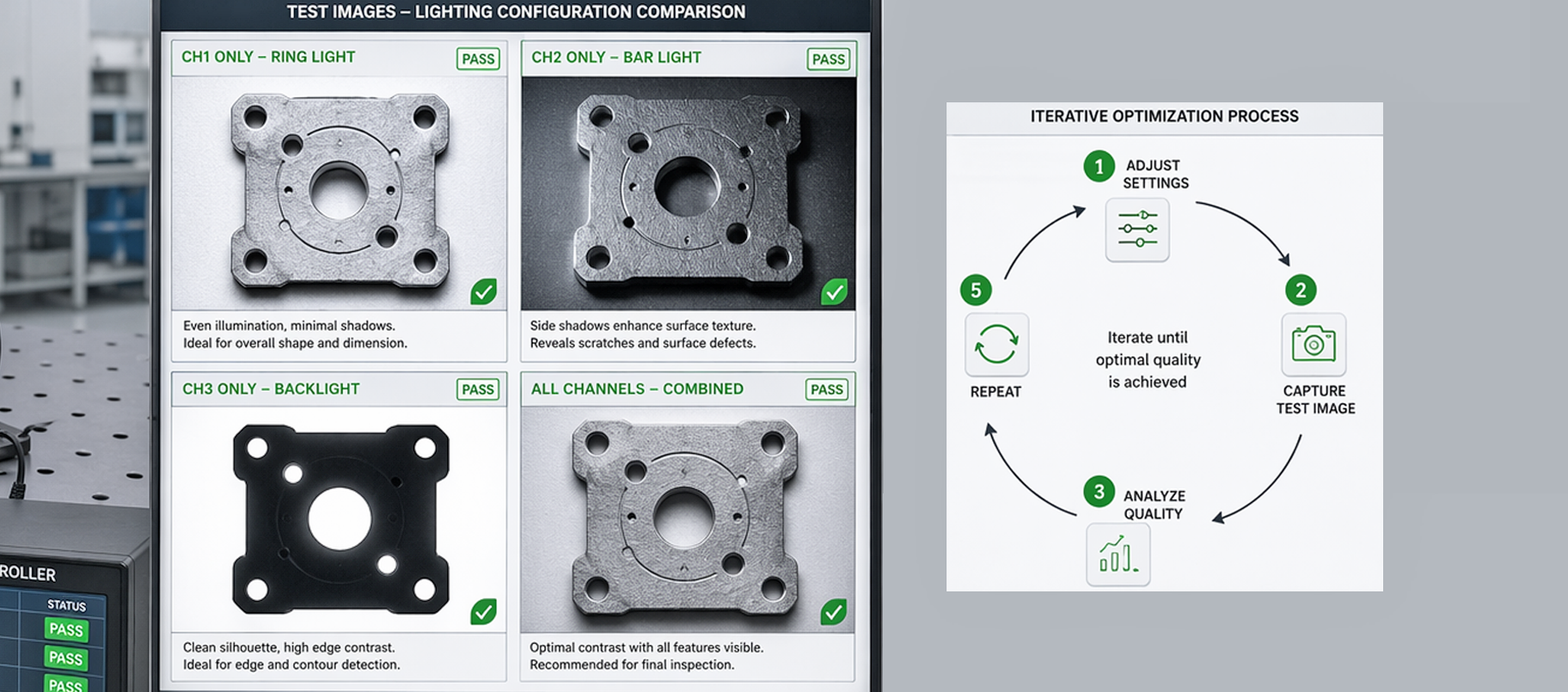
Once your machine vision light controller is physically installed and electronically connected, perform systematic testing of each channel output. Use an optical power meter or camera preview to verify that each channel on your machine vision light controller produces expected light intensity at the specified current level. Capture test images under each lighting configuration from your machine vision light controller to identify any flickering, dark spots, or uneven illumination that would degrade image quality.
During testing, adjust your machine vision light controller settings incrementally and observe how each change affects captured image quality, contrast, and defect visibility. Document the optimal settings on your machine vision light controller for each light source and product type so you can quickly recall these configurations during production troubleshooting or when training new operators on the vision system.
Diagnostics and Performance Tuning
Most machine vision light controller units include built-in diagnostic features that report channel status, current draw, temperature, and error conditions. Access the diagnostic interface on your machine vision light controller regularly to monitor system health and identify potential failures before they impact production quality. If your machine vision light controller reports overcurrent conditions, reduce the brightness setting or verify that light source connections are secure and undamaged.
Fine-tune the synchronization timing between your machine vision light controller and camera frame rate to maximize image brightness while minimizing exposure time and motion blur in fast-moving conveyor applications. This optimization directly improves the contrast and clarity of images captured under machine vision light controller illumination, enabling your vision algorithms to detect smaller defects and variations with greater confidence and fewer false positives.
FAQ
What are the main benefits of using a dedicated machine vision light controller instead of directly powering lights?
A dedicated machine vision light controller provides synchronized timing between lighting and image capture, precise intensity regulation that prevents image overexposure or underexposure, and independent channel control for multi-light setups. The machine vision light controller also protects your camera system from electrical noise and power surges by isolating light power circuits from sensitive imaging electronics, resulting in more reliable inspections and longer equipment lifespan in industrial manufacturing environments.
How do I determine the correct brightness settings for my machine vision light controller?
Begin with 50% brightness on your machine vision light controller and gradually increase or decrease intensity while monitoring captured images for optimal contrast and detail visibility. The ideal machine vision light controller brightness depends on your specific product surface reflectivity, defect type, camera sensor sensitivity, and ambient lighting conditions. Document the optimal brightness level on your machine vision light controller for each inspection task and save these profiles for consistent results across different production batches.
Can a machine vision light controller handle multiple light sources simultaneously?
Yes, most modern machine vision light controller models feature multiple independent output channels, allowing you to control several light sources with varying brightness and synchronization settings. Your machine vision light controller can power and coordinate ring lights, bar lights, backlighting, and directional spot lights all from a single unit, enabling sophisticated illumination strategies that enhance image contrast and defect detection accuracy across complex inspection scenarios.