EN
EN


Top 5 Machine Vision Light Mistakes to Avoid When Buying
Lighting is often one of the first components evaluated when building an automated inspection system, but it is easily underestimated. A high-resolution camera and advanced algorithms still fail if poor vision system illumination produces unstable images. This is why machine vision lighting must be treated as a core architectural requirement rather than a secondary accessory.
The selected light must match system power demands, triggering methods, operating environments, and structural constraints. Identifying common industrial lighting mistakes early reduces redesign work and ensures system stability during machine vision integration.
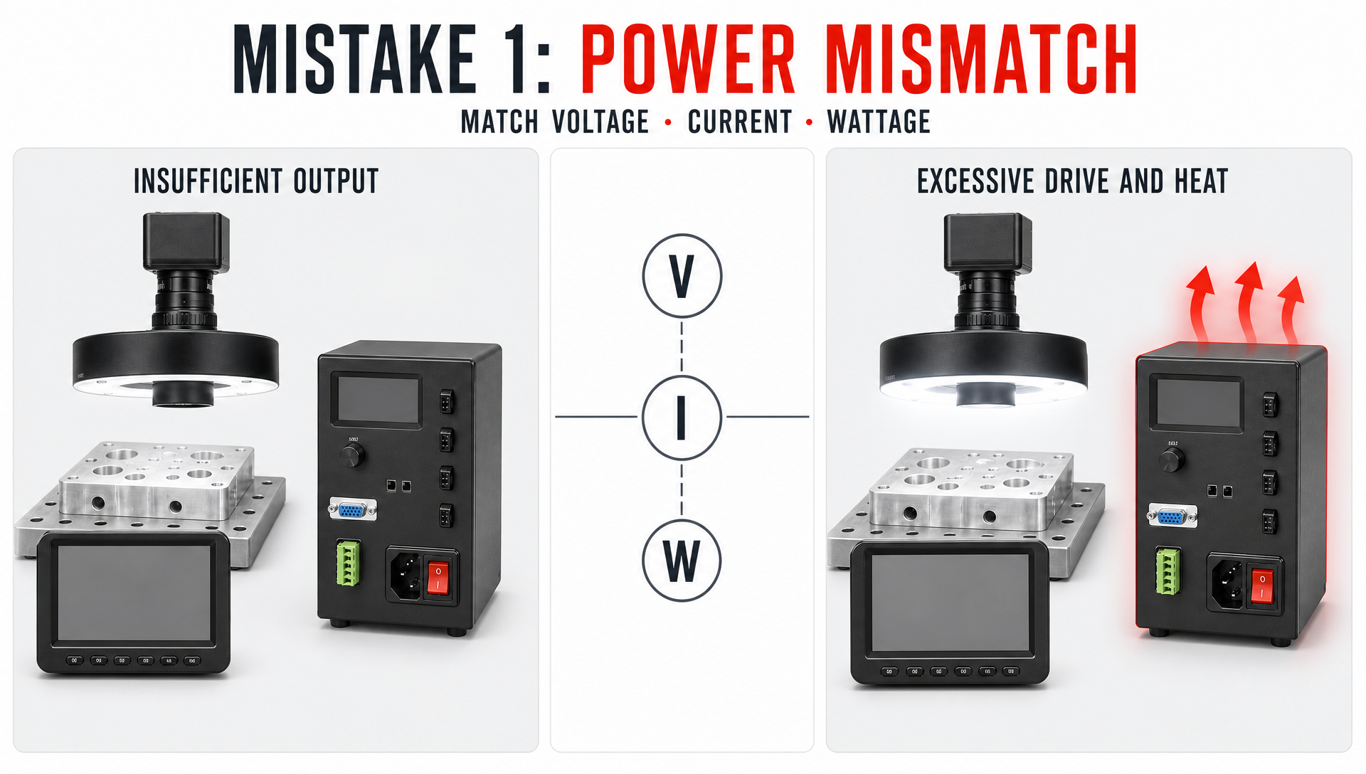
Mistake 1: Power Mismatch
Insufficient Output for the Lighting Load
Selecting a controller without checking the lighting load is a frequent mistake. If a light requires more power than the controller supplies, target brightness drops, obscuring critical defect details. Increasing camera gain to compensate introduces electronic noise and degrades image quality.
Power specifications must be calculated based on voltage, current, and wattage. In OEM machine vision setups using multiple light sources, total load capacity must be properly matched to avoid system instability.
Excessive Power and Thermal Overload
Choosing an oversized power supply introduces unnecessary complexity. Excess drive current generates extreme heat, requiring additional thermal management. Power capacity should be selected based on actual target reflectivity and duty cycles. For demanding applications, engineers should deploy a dedicated high-power lighting control solution.
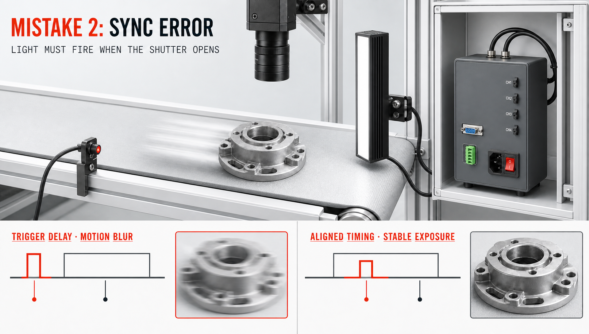
Mistake 2: Sync Error
Poor Coordination Between Light and Camera
Timing synchronization is critical when inspecting moving parts. In high-speed OEM machine vision systems operating at short exposure times, slight trigger delays cause image flicker and motion blur. Verifying response times to external hardware triggers ensures stable exposure across production cycles.
Defining Triggering Requirements Early
Triggering requirements depend on PLC timing, camera models, and line speed. Defining trigger modes—whether basic external triggers or stroboscopic pulses—prior to machine vision integration ensures lighting fires precisely when the camera shutter opens.
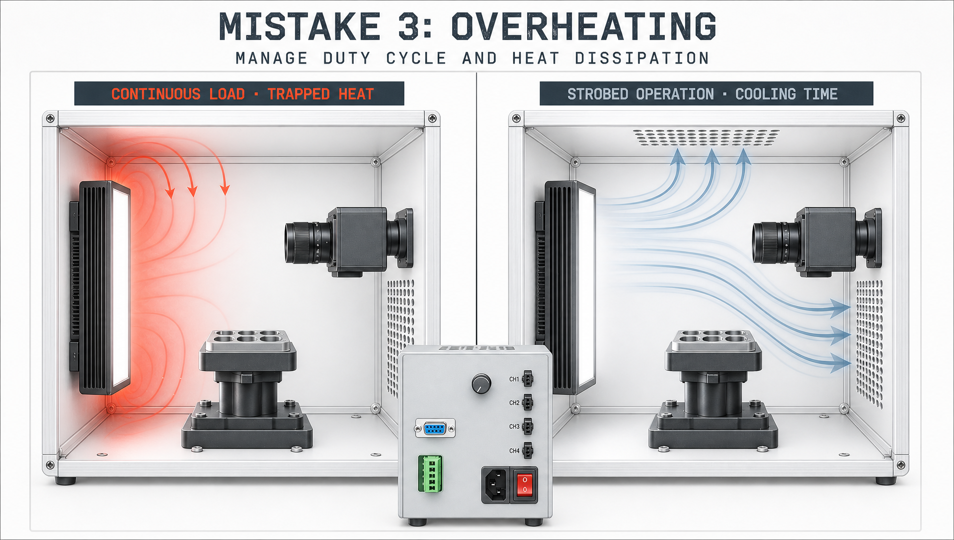
Mistake 3: Overheating
Thermal Considerations for High-Output Lighting
Ignoring thermal dissipation causes serious long-term reliability issues. High-output LEDs convert electrical energy into heat, which degrades luminous efficiency and shortens hardware lifespans if trapped inside compact enclosures.
Duty Cycle and Cooling Strategies
Strobed operation allows LEDs to cool between pulses, whereas continuous lighting applies constant thermal stress. Evaluating production duty cycles and ambient factory temperatures ensures passive heat sinks or active cooling are appropriately configured.
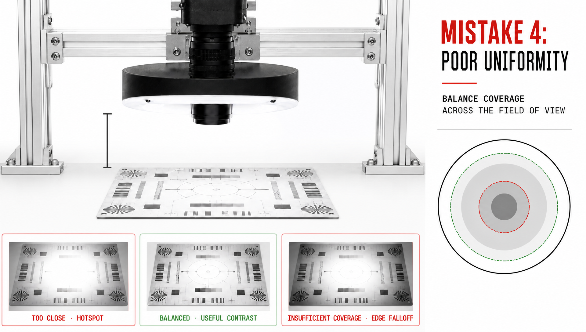
Mistake 4: Poor Uniformity
Uneven Illumination Degrades Image Quality
Raw intensity cannot replace spatial uniformity. Light falloff near image boundaries causes edge defects to go undetected while identical center features trigger false rejects. Quality vision system illumination ensures balanced contrast across the entire field of view.
Lighting Geometry and Placement Angle
Fixture positioning governs light distribution. Mounting lights too close causes hotspots, while mounting too far reduces lux. Exploring HIFLY's machine vision lighting product range helps engineers match optical geometries—such as ring, dome, or backlights—to target surface characteristics.
Mistake 5: Integration Lock-In
Ignoring the Complete Vision Architecture
Evaluating lights separately from cameras, lenses, PLCs, and mounting frames leads to integration bottlenecks. Successful machine vision integration requires accessible cabling, compact footprints, and seamless controller communications.
Building Flexible Lighting Configurations
Production changes often require supporting new part sizes or colors. Choosing flexible multi-channel hardware avoids costly mechanical overhauls. Incorporating a multi-channel lighting control option simplifies multi-head triggering and sequence management.
Additional Factors for Automated Inspection Lighting
Working Distance and Field of View Constraints
Working distance dictates light falloff and beam spread. Matching fixture coverage to lens field of view prevents vignetting without wasting power outside the camera frame.
Surface Material and Reflection Properties
Substrates interact uniquely with light. Reflective metal and glass demand diffuse or coaxial lighting to prevent glare, dark materials require high intensity, and textured surfaces benefit from low-angle grazing light. Matching geometry to material physics prevents critical industrial lighting mistakes.
A Practical Selection Process
Start With the Inspection Objective
Define inspection targets first—whether measuring dimensions, detecting scratches, or reading OCR text. Evaluate material reflectivity, working distance, and camera shutter parameters before selecting fixtures.
Test the Complete Physical Setup
Datasheets cannot replace benchtop testing. Testing real samples using actual cameras, lenses, and light positions identifies glare and threshold issues before finalizing mechanical designs.
Choosing a Suitable Lighting Solution
Matching Performance With Integration
The optimal light source provides reliable contrast while fitting smoothly into machine architectures. Power, timing, thermal management, and uniformity must align for long-term industrial operation.
Supporting Diverse OEM Machine Vision Applications
OEM machinery requires adaptable hardware. HIFLY supplies high-performance machine vision lighting fixtures and controllers engineered for demanding industrial inspection environments.
Conclusion
Avoiding the five major industrial lighting mistakes—power mismatch, sync error, overheating, poor uniformity, and integration lock-in—requires treating lighting as a primary system component. Thorough prototyping and early parameter matching ensure successful machine vision integration.
FAQ
What is the most common machine vision lighting mistake?
Power mismatch. Under-powering degrades image contrast, while over-powering causes thermal issues and excessive heat buildup.
Why is lighting synchronization critical in OEM machine vision?
In high-speed production, lights must fire in microsecond alignment with camera shutters to prevent motion blur and exposure variations.
How can overheating be prevented in vision system illumination?
Optimize duty cycles via strobing, select proper controller power ratings, ensure adequate heat dissipation space, and avoid continuous overdrive.
How can poor lighting uniformity be corrected?
Test fixtures at the actual working distance and deploy suitable optical structures, such as diffuse domes, backlights, or coaxial lights.