EN
EN


Can a high-speed machine vision camera capture micron-level defects on moving production lines?
When production lines run at high speed, even the smallest surface flaw can compromise product quality, trigger costly recalls, or damage a brand's reputation. The question many manufacturers ask is whether a machine vision camera can realistically capture defects measured in microns while parts, sheets, or components fly past at industrial speeds. The short answer is yes — but only when the right hardware, optics, and system architecture are matched to the specific inspection challenge.
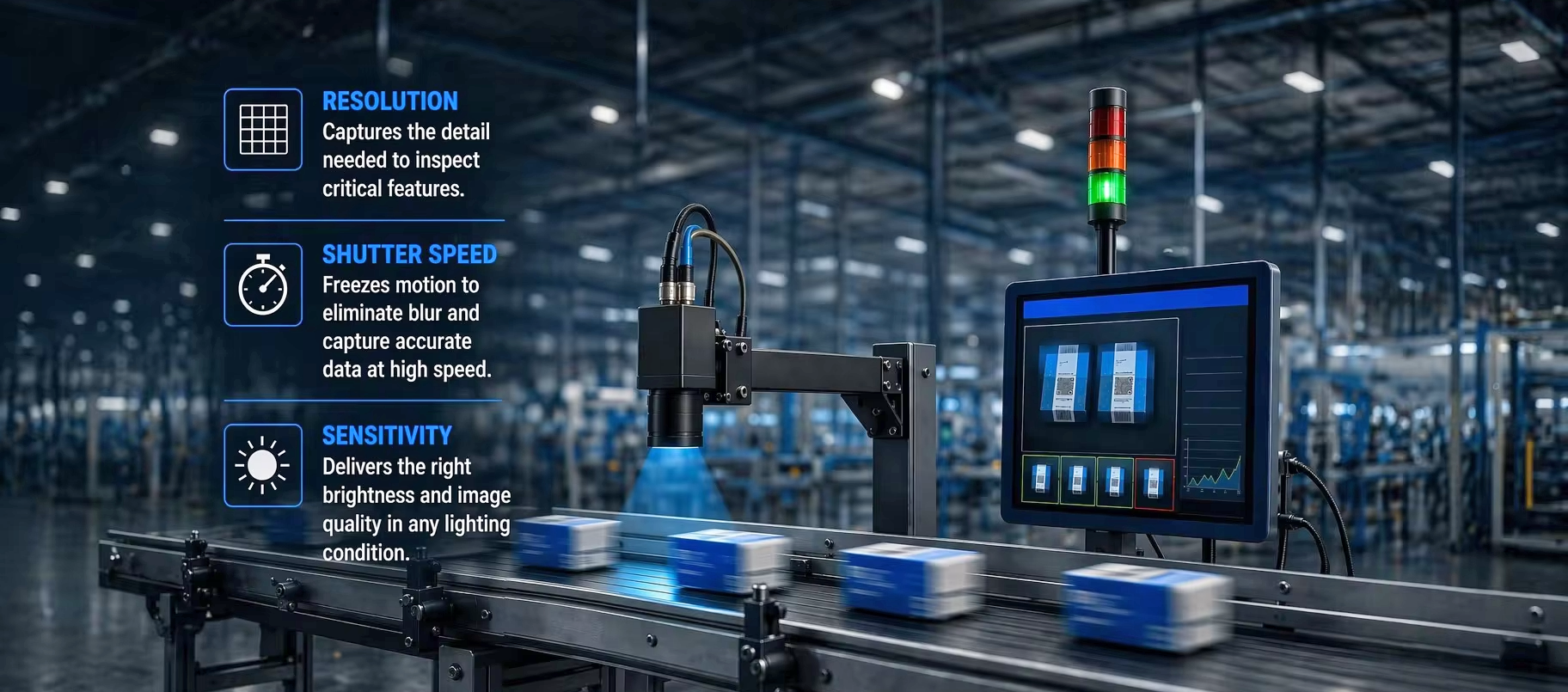
A machine vision camera used in industrial inspection must balance three critical performance pillars: resolution fine enough to resolve micron-scale features, shutter speed fast enough to freeze motion without blur, and sensitivity sufficient to distinguish subtle contrast differences that reveal surface anomalies. Understanding how these pillars interact is essential before deploying a machine vision camera on any high-throughput production line.
Resolution and Sensor Design in a Machine Vision Camera
Pixel Size and Optical Magnification
The ability of a machine vision camera to detect micron-level defects depends directly on the relationship between pixel size, sensor resolution, and the optical magnification applied at the lens. A machine vision camera with smaller pixels and a higher megapixel count can resolve finer spatial detail across the same field of view. In practical terms, this means that a machine vision camera equipped with a high-resolution sensor — such as an 8-megapixel or higher model — can map a one-meter web to individual pixel-level precision when paired with appropriate optics. Every micron-scale scratch, pit, or inclusion that falls within one pixel or more becomes detectable by the machine vision camera system.
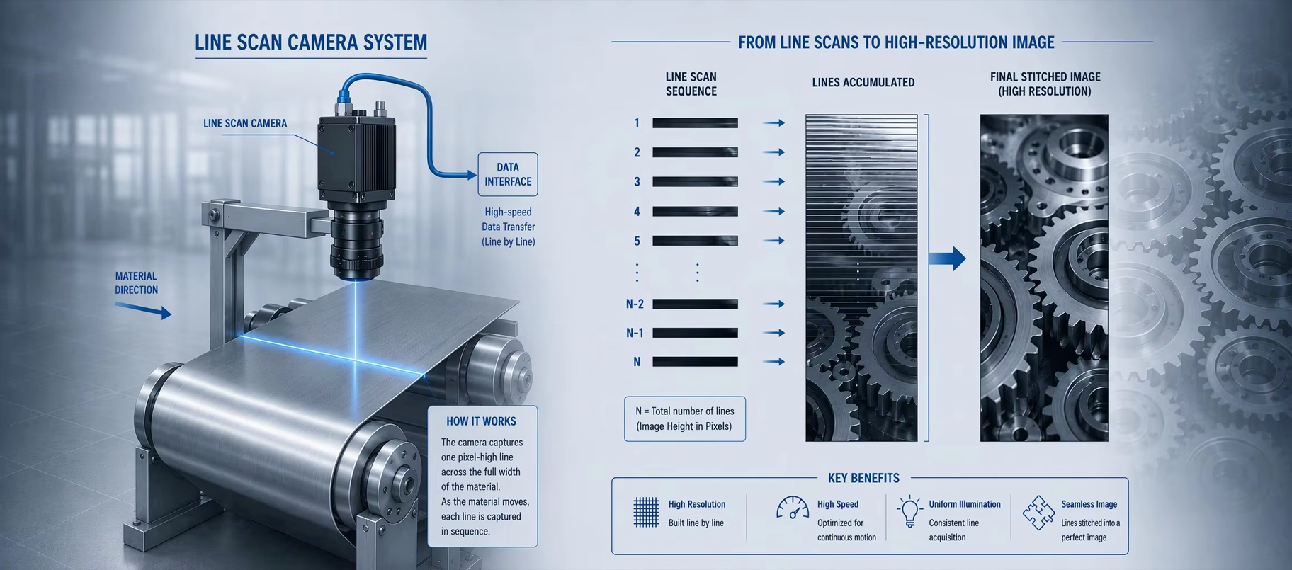
Line scan technology is a particularly effective approach for a machine vision camera targeting continuous material inspection. Rather than capturing a two-dimensional frame, a line scan machine vision camera reads one narrow line of pixels at a time as the material moves beneath it. This allows the machine vision camera to build a seamless, high-resolution image of any length of material without the field-of-view limitations that constrain area scan sensors. For applications such as metal strip, printed film, or woven fabric, a line scan machine vision camera remains the preferred industrial solution.
Sensor Format and Field Coverage
Sensor format affects how much area a machine vision camera can cover without sacrificing resolution. A larger sensor format allows the machine vision camera to maintain high pixel density across a wider inspection zone. When engineers need to inspect wide substrates at speed, selecting a machine vision camera with a large-format sensor ensures that no portion of the surface escapes the detection window. The machine vision camera must be specified so that its ground sampling distance — the physical size each pixel represents on the product — falls below the minimum defect size that quality standards require the system to catch.
Speed, Motion Blur, and Exposure Control
How Shutter Mechanisms Affect a Machine Vision Camera on Moving Lines
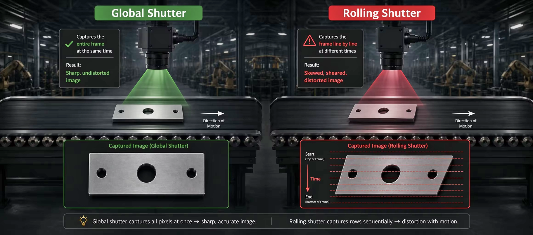
Motion blur is one of the most common causes of missed detections in a machine vision camera deployment. If the exposure time is too long relative to how fast the target is moving, the machine vision camera captures a smeared image rather than a sharp one. At line speeds of 100 meters per minute or more, the machine vision camera must expose in microseconds to freeze motion effectively. A machine vision camera with a global shutter captures the entire sensor simultaneously, eliminating the rolling-shutter distortion that would otherwise misrepresent fast-moving features. For most demanding industrial applications, a global shutter machine vision camera is the correct choice when defect geometry must be precisely preserved.
Line scan machine vision camera designs naturally avoid this problem because each line is exposed independently as new material arrives. The machine vision camera integrates light from a very thin slice of the product for only a brief moment. By synchronizing the machine vision camera's line rate to the conveyor or web speed through an encoder signal, the resulting image maintains true spatial proportions regardless of how fast the line is running. This synchronization is one reason a machine vision camera built on line scan architecture excels in defect detection on continuous-process production lines.
Lighting and Contrast Optimization
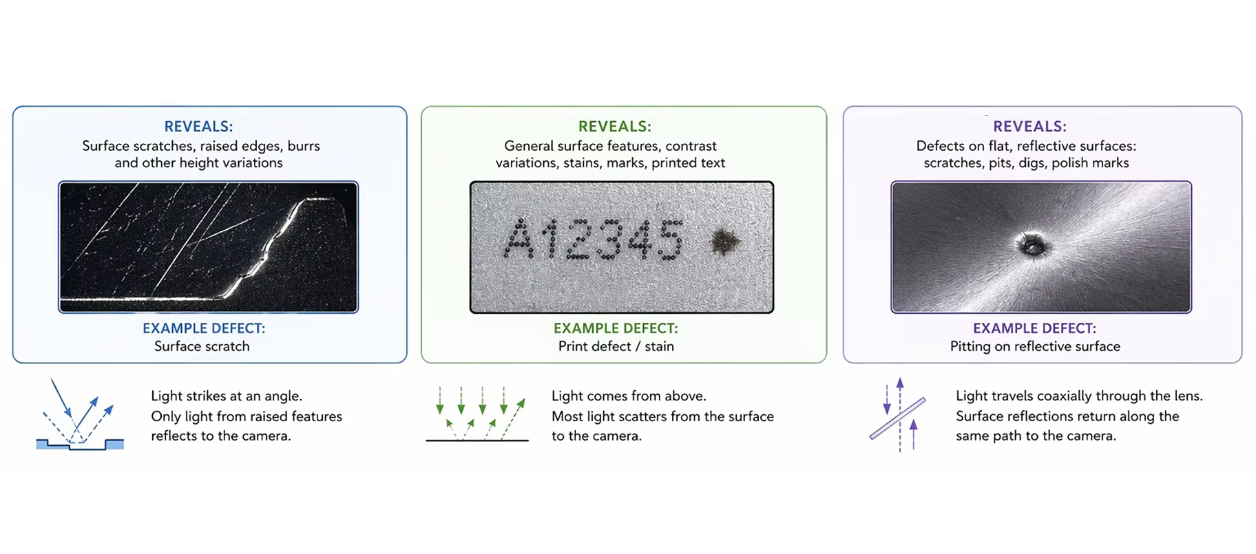
Even the most advanced machine vision camera cannot detect what it cannot see. Lighting design is inseparable from machine vision camera performance in micron-level inspection. Structured illumination — such as dark field, bright field, or coaxial light — is selected based on the defect type and surface texture. A machine vision camera receiving dark-field illumination can reveal surface scratches and raised edges that would be invisible under diffuse lighting. When the lighting is optimized, the machine vision camera converts subtle physical variations into strong grayscale or color contrast, making algorithmic detection far more reliable. The machine vision camera and the lighting system must be engineered as a unit, not as separate afterthoughts.
System Integration for Micron-Level Inspection
Interface Speed and Data Throughput
A machine vision camera generating high-resolution images at speed produces enormous volumes of data. The interface connecting the machine vision camera to the processing computer must be fast enough to transfer this data without bottlenecks. Modern machine vision camera platforms support interfaces such as 10GigE, which can sustain continuous high-bandwidth transfers suitable for demanding inspection rates. When the machine vision camera interface is undersized for the data rate, frames are dropped and defects go undetected. Selecting a machine vision camera with an interface matched to the application's throughput requirements is a non-negotiable design decision.
Software and Defect Classification Algorithms
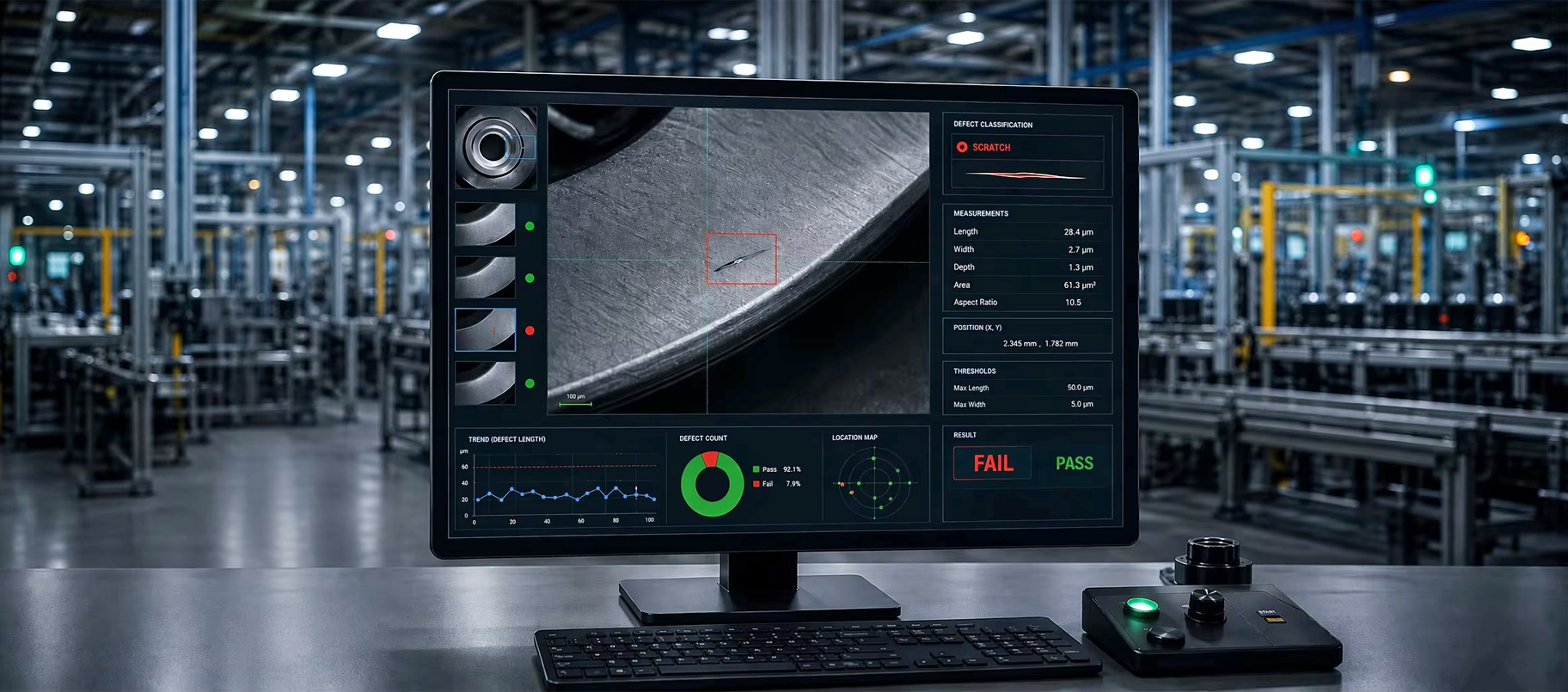
The machine vision camera delivers pixel data, but it is the inspection software that translates that data into actionable quality decisions. Algorithms paired with a machine vision camera can classify defect type, measure defect dimensions, and determine whether a part should pass or fail — all in real time. Modern machine vision camera systems increasingly support deep learning models that improve detection accuracy on complex or variable defect patterns. The machine vision camera hardware and the software intelligence together define what the system can ultimately achieve in a production environment. A well-configured machine vision camera with advanced image analysis can reliably distinguish a 10-micron scratch from a benign surface texture variation at line speed.
FAQ
What resolution does a machine vision camera need to detect micron-level defects?
The required resolution of a machine vision camera depends on the minimum defect size and the field of view. As a practical rule, the machine vision camera should be specified so that the smallest defect spans at least two pixels. For micron-level inspection, this often means selecting a machine vision camera with pixel sizes below five microns and high overall megapixel counts, combined with appropriate magnifying optics.
Is a line scan machine vision camera better than an area scan model for moving lines?
For continuous materials such as webs, sheets, and strips, a line scan machine vision camera is typically the better choice. It builds images progressively as material moves, allowing the machine vision camera to inspect unlimited lengths at consistent resolution. An area scan machine vision camera is better suited to discrete parts where the object can be stopped or strobed within a fixed frame.
How does lighting affect machine vision camera defect detection accuracy?
Lighting directly determines the contrast a machine vision camera captures between a defect and the surrounding surface. Without optimized illumination, even a high-resolution machine vision camera will miss low-contrast anomalies. The correct lighting geometry — dark field, bright field, or diffuse — must be matched to the defect type and material surface so that the machine vision camera receives the maximum possible signal difference at the defect location.