

How to Optimize Exposure Using a Machine Vision Light Controller
Why Exposure Optimization Starts with the Machine Vision Light Controller
Exposure as a system-level variable—not just camera settings
Getting good exposure isn't just about adjusting camera settings either. It's really about how all the components work together, especially when it comes to controlling light. The machine vision light controller handles things like brightness levels, how long lights stay on, and timing coordination. This creates better contrast than what shutter speed and aperture can manage alone. When dealing with shiny surfaces or materials that don't show much contrast, like polished metal parts, proper lighting makes around 70% difference in image quality according to some research from IEEE back in 2022. For those fast moving production lines, getting strobes and cameras synced within fractions of a microsecond matters a lot if we want to avoid blurry images. Smart lighting systems basically turn chaotic lighting situations into consistent imaging conditions, which is why they form the base for spotting defects reliably in manufacturing processes.
The exposure budget triangle: shutter speed, gain, and controllable light intensity
Getting the right exposure involves balancing three key factors together: shutter speed, sensor gain settings, and how much light we can actually control. When we go for faster shutter speeds, we get rid of motion blur problems but need way more light to make it work. Boosting the gain makes things brighter but introduces noise into the image which hurts measurement accuracy quite a bit around ISO 1600 according to tests done under EMVA 1288 guidelines. That's where modern light controllers come in handy. They solve these conflicting requirements by sending out short bursts of intense light exactly when needed. Take those super fast 100 microsecond exposures for example. These require about four to five times more light intensity compared to regular continuous lighting setups. This approach lets us keep the gain low enough without triggering motion artifacts. The result? A much bigger window of opportunity for capturing tricky materials such as glass surfaces or textured plastic parts where too much gain just washes out the tiny details that matter most during quality checks.
Key Lighting Parameters Impacting Exposure
|
Parameter |
Impact on Exposure |
Industrial Application Benefit |
|
Intensity |
Compensates for short shutter speeds |
Enables 500+ FPM inspection without motion blur |
|
Strobe Duration |
Controls motion freeze capability |
Captures fastener threads at 1,200 RPM |
|
Synchronization |
Eliminates rolling shutter distortion |
Verifies PCB solder joints at 10 µm resolution |
|
Wavelength |
Enhances material-specific contrast |
Detects hairline cracks in transparent polymers |
Precision Timing Control: Synchronizing LED Strobe and Camera Trigger via Machine Vision Light Controller
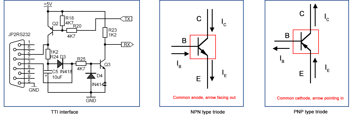
Sub-microsecond trigger latency: TTL/NPN/PNP interface benchmarks and real-world jitter impact
For high speed synchronization applications, getting sub microsecond trigger latency just isn't optional anymore. TTL interfaces still hold the crown for fastest response times under 200 nanoseconds, though they come with the headache of needing exact voltage matches across equipment. The NPN setup gives us around 300 to 500 nanoseconds delay but handles electrical noise much better than alternatives. PNP options match those timing specs too, but work with inverted logic signals which can trip up newcomers. Real world factories face another challenge though - electromagnetic interference often creates timing variations over 100 nanoseconds. That kind of jitter shows up as motion blur problems on conveyors running at five meters per second. When trying to capture clear images of things like semiconductor wafers zipping by or pharmaceutical capsules on production lines, this inconsistency becomes a major obstacle for quality control teams.
Strobing strategies for ultra-short exposures (<100 µs): duty cycle, peak intensity, and flickerless operation
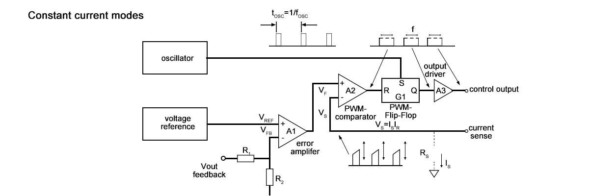
For exposures under 100 µs, a 1–5% duty cycle enables up to 3.2× peak intensity gain through controlled LED overdrive—leveraging the light controller’s constant-current regulation to sustain microsecond bursts without visible flicker. Thermal constraints scale predictably with pulse duration:
|
Parameter |
<50 µs |
50–100 µs |
Risk Factor |
|
Peak Current |
3–4× rated |
2–3× rated |
LED degradation |
|
Duty Cycle |
≤3% |
≤5% |
Thermal runaway |
|
Stability Window |
±0.5% |
±1.2% |
Intensity drift |
Flickerless operation requires driving frequencies above 5 kHz—well beyond typical camera integration times—to prevent banding artifacts in high-speed bottling or PCB inspection lines. Crucially, junction temperatures above 85°C reduce LED lifespan by 30% per 10°C increase (Lumileds, 2023), underscoring the need for thermal-aware pulsing strategies.
Boosting Signal-to-Noise Ratio: Overdrive and Constant-Current Modes in Machine Vision Light Controllers
LED overdrive trade-offs: 3.2× intensity gain at 5% duty cycle vs. thermal and lifetime constraints
Overdriving LEDs means sending pulses of current that go beyond what they're rated for, but only for very brief periods. This technique helps boost signal-to-noise ratios when using sophisticated light controllers. When running at about 5% duty cycle, we can get intensity gains of around 3.2 times normal levels, which makes all the difference in those fast inspection scenarios where every detail matters. The downside? There are real heat issues to contend with. Junction temperatures can jump as much as 40 degrees Celsius during these overdrive periods, causing LEDs to degrade roughly 75% faster than under regular operating conditions according to IEC 62717 tests on reliability. To combat this problem, constant current modes come into play, maintaining steady output without any flickering even during extended or longer pulse operations. This keeps images clear and results consistent across multiple runs. A few important things need attention here though:
- Peak intensity vs. longevity: Duty cycles exceeding 10% risk irreversible lumen depreciation
- Thermal mitigation: Pulsed operation below 100 µs or active cooling prevents thermal runaway
- Lifetime optimization: Derating curves show 30% lumen loss occurs five times faster at 150°C versus 85°C junction temperature
Balancing these ensures sustained SNR gains without compromising long-term system reliability.
Sustaining Performance: Thermal Management and Duty Cycle Limits for High-Speed Machine Vision Light Controllers
Junction temperature derating curves and their direct effect on usable exposure window stability
The derating curves for junction temperatures, which are set by LED makers, basically tell us what's the top drive current we can push through LEDs at different temps. When folks ignore these guidelines, they end up with faster LED wear out and those pesky lumen variations that can jump over 12% when running in pulse mode. This kind of instability really cuts down on our usable exposure window, that brief period where light stays uniform enough for good image capture. For applications needing microsecond exposures, even small changes in temperature will mess with intensity uniformity and boost inspection errors as much as 18%, according to some research from 2021 by the Optoelectronic Reliability Consortium. To keep things running smoothly over long production periods, operators need to stay under those derating limits. That means investing in proper cooling systems and keeping duty cycles tight, usually staying below 25% for those high current pulses.
From Manual Tuning to Co-Design: Automated Exposure–Lighting Optimization with Machine Vision Light Controllers
Back in the day, getting good exposure meant going through all sorts of trial and error with lights and camera settings. People would tweak things manually again and again until they got it right, but this approach was full of inconsistencies and prone to mistakes made by tired technicians. Modern top tier systems take a different approach altogether. They follow what's called co design principles where special machine vision light controllers work hand in hand with cameras. These controllers adjust the lighting automatically based on real time feedback from the camera itself. Instead of just fiddling with individual components separately, everything works together as part of a bigger picture. The whole system behaves more like a well oiled machine rather than a collection of separate parts trying to do their own thing.
Digital twin workflows: integrating Zemax OpticStudio simulations with HALCON exposure modeling
Engineers now build digital twins of vision systems by fusing optical simulation tools like Zemax OpticStudio with HALCON’s exposure modeling engine. This virtual environment enables:
- Predictive assessment of how lighting parameters affect image quality—before physical prototyping
- Simulation of complex interactions among strobe timing, material reflectivity, and sensor response
- AI-driven automation of lighting-intensity adjustments that continuously maximize contrast
By evaluating hundreds of lighting configurations in minutes—not days—manufacturers cut deployment cycles by 40% and eliminate costly trial-and-error iterations. Critically, the digital twin ensures consistent illumination quality across production lines by programmatically embedding optimal configurations directly into the machine vision light controller firmware.