

Machine Vision Lens Selection Guide for Industrial Applications
Key Optical Parameters: FOV, Working Distance, and Focal Length
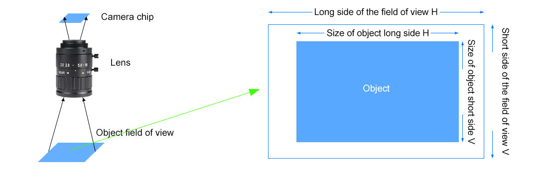
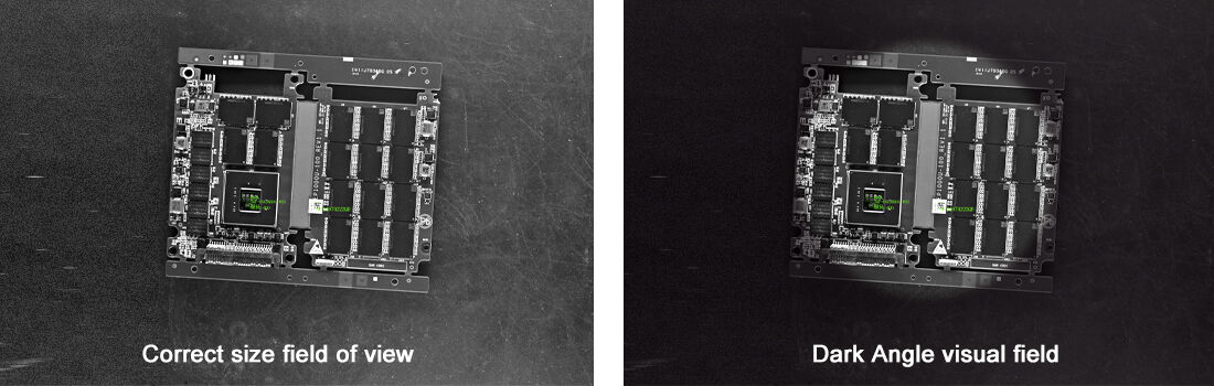
How Field of View (FOV) Determines Machine Vision Lens Suitability for Assembly Line Inspection
The field of view, or FOV for short, basically tells us what area a camera can actually see at once, which matters a lot when inspecting products on assembly lines. If the FOV is too tight, small defects along the edges might get missed entirely. On the flip side, going too broad means each pixel covers more ground, so details start to blur out and resolution drops off. There's this handy formula to figure it all out: multiply sensor size by working distance then divide by focal length. Let's say someone needs to cover everything with a 100mm sensor. They'd probably need either to get closer to the object or pick a different lens altogether based on how much space they have available. According to some industry reports floating around, almost a third of all problems with vision systems come down to getting the FOV wrong initially. Getting this right makes sure every inch of parts gets scanned properly without those pesky motion artifacts messing things up, which ultimately helps spot defects faster during fast paced manufacturing runs.
Working Distance and Focal Length Interplay in Robotic Guidance and Embedded Vision Setups
The relationship between working distance (the gap between lens and object) and focal length works in reverse, which really matters when it comes to robotic guidance systems and embedded vision tech. When we need longer working distances, the focal length has to go up too if we want to keep things in focus - something critical for robots moving around safely without bumping into stuff. But there's always a catch. Increasing focal length actually makes the depth of field narrower, so getting everything just right becomes a calibration nightmare. For those tight spaces where equipment like PCB inspection tools must fit, shorter focal lengths let us get closer to objects while still seeing what needs to be seen. Getting this balance right helps reduce motion blur when things are moving fast. Industry tests show that every time focal length goes up, lateral resolution jumps somewhere between 15% to 30%, which means these systems can hit targets down to the micron level for automated guidance jobs.
Sensor Compatibility and Mount Standards for Reliable Machine Vision Lens Integration
Image Circle Coverage vs. Sensor Size: Why Mismatched Machine Vision Lens Selection Causes Vignetting and Resolution Loss
Getting the wrong machine vision lens for a sensor because it doesn't cover enough area leads to major optical problems down the line. If the lens projects an image circle smaller than what the sensor needs, we see something called vignetting where the corners get really dark sometimes dropping light levels by as much as 80%. That means losing valuable data from those edges completely. What happens next is even worse for resolution. Take a 12 megapixel sensor matched with a lens designed for just a 1/1.8 inch format? The real world performance drops off to around 8 megapixels max. For folks working on printed circuit boards, this kind of shortfall can hide tiny cracks measuring less than 10 microns wide. A good rule of thumb when shopping for lenses is to check if their specs mention image circle coverage that beats the sensor diagonal measurement by about 10% minimum.
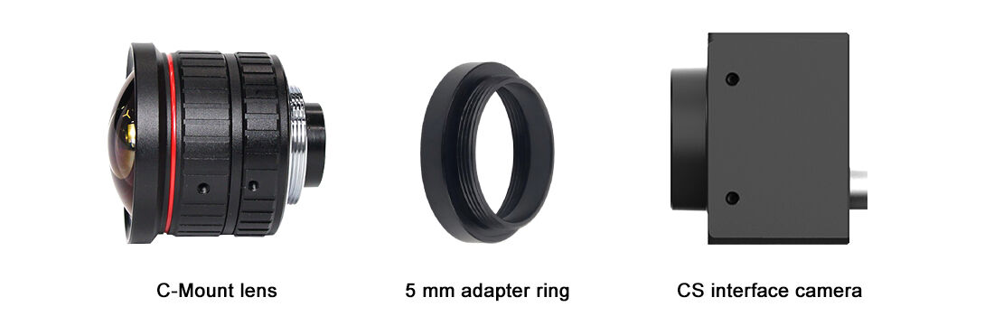
C-Mount vs. CS-Mount: Mechanical Fit, Back Focal Distance, and Real-World Constraints in Compact Systems
The threads on C-mount lenses (with a flange distance of 17.526mm) and CS-mount lenses (at 12.526mm) work together mechanically, though they have significant differences when it comes to back focal distance. When someone tries to force a CS-mount lens onto a C-mount camera, this creates about 5mm of defocus which can blur tiny details down to 0.1mm tolerances. That kind of problem happens all the time in robotic pick and place operations. On the flip side, putting a C-mount lens on a CS-mount camera body needs special spacers that actually make things less stable, especially important in those embedded systems that experience vibrations constantly. Medical device manufacturers know this well because their equipment often has to fit inside really tight spaces around 50 cubic millimeters. The smaller size of CS-mount makes focusing possible in these situations where C-mount just won't reach. Most folks stick with standard practices to avoid headaches during installation. Typically, CS-mount is used for sensors smaller than half inch, while bigger sensors go with C-mount.
Aperture, Depth of Field, and Critical Optical Performance Metrics
F-Number Optimization: Balancing Light Throughput, Depth of Field, and Motion Blur in High-Speed Inspection
In industrial machine vision systems, the f-number (f/#) controls three important factors at once: how much light gets through the lens, the depth of field (DOF), and how resistant the image is to motion blur. When we set lower f-numbers like f/1.4, they let in a lot more light which is great for dim conditions, but comes at a cost. The depth of field becomes really shallow, so if there are any irregularities in surface height across what's being inspected, parts might fall out of focus. On the flip side, higher numbers such as f/16 give us much better depth of field coverage needed for accurate dimensional measurements. However, this requires longer exposure times which makes images more prone to motion blur problems, especially when dealing with fast moving items on conveyors running at speeds above 1/10,000 seconds per frame. Finding the sweet spot between these competing needs takes careful consideration of both lighting conditions and production requirements.
- Calculate hyperfocal distance to maintain focus across tolerance zones
- Match aperture to strobe intensity—over 50,000 lux allows Æ'/8+ without noise penalty
- Prioritize Æ'/4—Æ'/8 for >92% of high-speed applications (Automated Imaging Association, 2023)
Balancing these factors prevents false rejects while sustaining throughput above 300 ppm.
MTF, Distortion, and Contrast—How Machine Vision Lens Specifications Directly Impact Defect Detection Accuracy
The ability to detect defects reliably depends on several factors including Modulation Transfer Function or MTF, levels of distortion, and how good the contrast is between objects. When MTF readings stay above 0.6 at what's called the sensor's Nyquist frequency, we get edge measurements within about half a pixel accuracy which matters a lot when looking for tiny cracks just a few microns across. Keeping distortion below 0.1 percent helps avoid those annoying geometry errors that happen during measurement work. And having strong contrast ratios over ninety to one makes all the difference in spotting small issues such as oxidation marks against complex background textures. These parameters aren't just numbers on paper they actually impact real world inspection results every day.
|
Parameter |
Defect Detection Impact |
Tolerance Threshold |
|
MTF @ 50 lp/mm |
Scratch visibility |
≥0.45 |
|
Radial Distortion |
Dimensional error |
≤0.15% |
|
Contrast Ratio |
Contaminant detection |
≥80:1 |
Sub-optimal MTF or >0.3% distortion causes 37% false negatives in PCB inspection (Vision Systems Design, 2024). Thus, machine vision lens specifications directly dictate quality control accuracy.
Specialized Machine Vision Lens Types for Precision Industrial Tasks
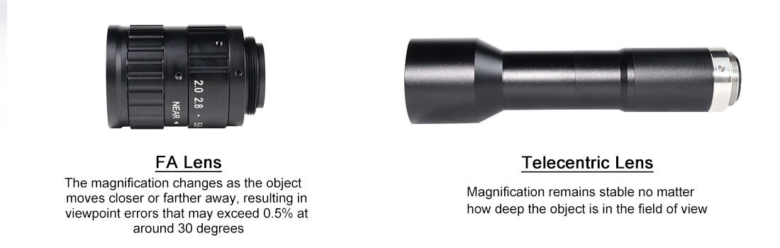
Telecentric Lenses in Metrology: Eliminating Perspective Error for Sub-Pixel Measurement Stability
Telecentric lenses are absolutely essential for industrial metrology applications that require sub-pixel level stability in measurements. Regular lenses have a problem where the magnification changes as objects move closer or farther away, creating perspective errors that can go beyond 0.5% at around 30 degree angles. With telecentric optics, all those chief rays stay parallel instead. This means the magnification stays consistent no matter how deep an object is in the field of view. It makes all the difference when checking things like PCB pad alignment or gear tooth profiles, where even tiny distortions at the micron level can ruin product quality. For automated gauge checks, these lenses deliver repeatable measurements down to plus or minus 0.01mm because they eliminate those pesky scaling errors from perspective issues. Plus, since there's no angular distortion to worry about, calibration becomes much easier. Setup times drop somewhere between 30 and 40 percent compared to regular lenses in precision manufacturing settings.
Ready to Select the Right Machine Vision Lens?
The right lens balances the field of view (FOV), working distance, sensor compatibility, and performance metrics to match your industrial application. Avoiding mismatches and prioritizing key specifications ensures reliable defect detection and measurement accuracy.
For lens - camera compatibility guidance, specialized options (e.g., telecentric lenses), or custom adaptation services, partner with a provider with proven industrial experience. HIFLY's 15 years of machine vision expertise—spanning lenses, cameras, and integrated solutions—ensures alignment with your production demands. Contact us today for a no - obligation consultation to refine your lens selection.